Roland SolJet PROII SC-540 Скачать руководство пользователя страница 79

77

Chapter 4 - Maintenance

4-1 Cleaning the Printing Heads

If Drop-out Persists Even After Carrying Out Cleaning Several Times
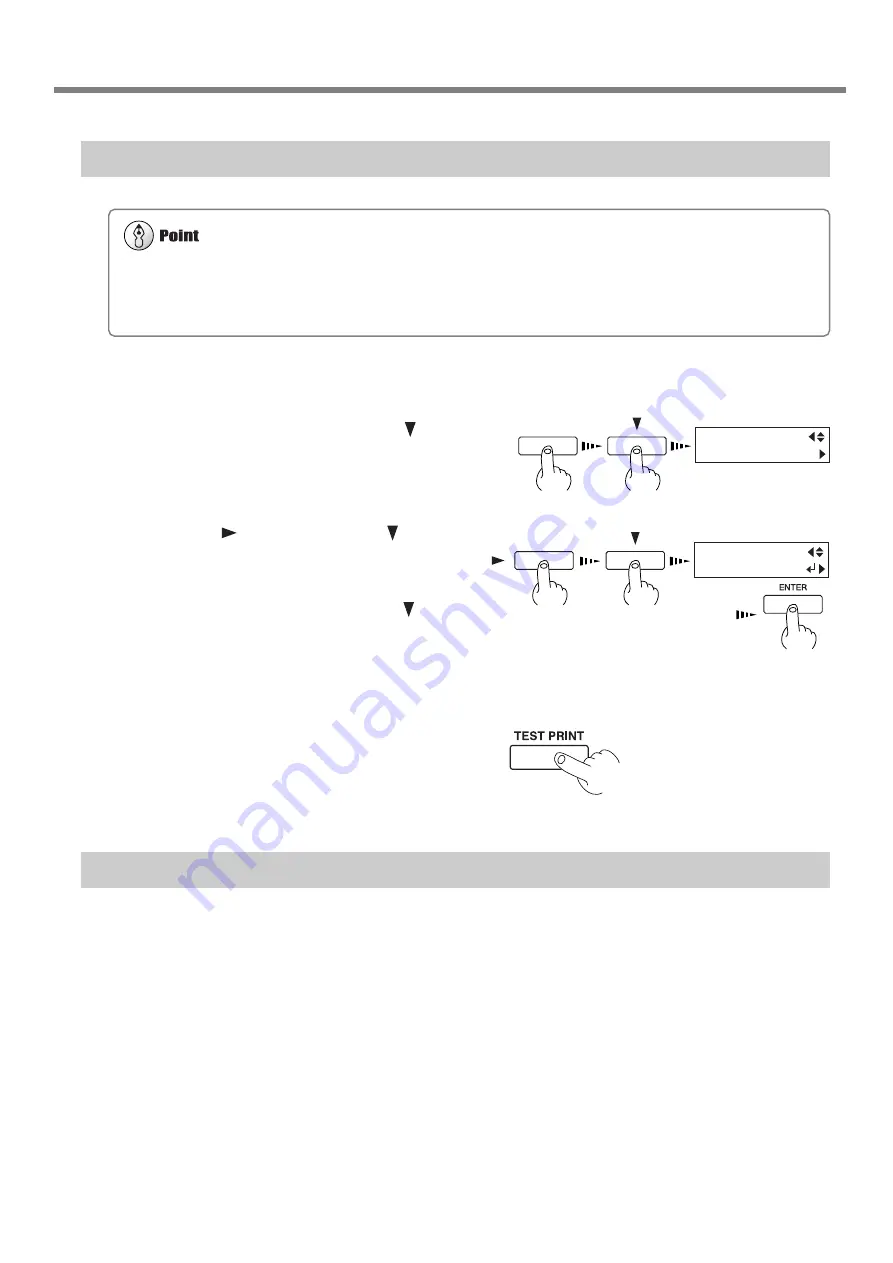
1

Load media for printing-test use.

2

Press the [MENU] key, and press the [   ] key
to make the following screen appear on the dis-
play.

3

Press the [ 

 ] key, and press the [   ] key to

display the screen shown in the figure.

You can choose to perform cleaning of only the
A group heads, B group heads, C group heads
or only the left head by pressing the [   ] key
more times.

Press the [ENTER] key to start head cleaning
("medium").

4

When head cleaning finishes, perform a print-
ing test to check the results.

If Performing POWERFUL Cleaning Several Times Does Not Correct the Drop-out Problem

If performing cleaning several times at the [POWERFUL] menu does not correct the image drop-out problem, use the
included cleaning kit. For information on how to use the cleaning kit, refer to the following section, "Cleaning Using the
Cleaning Kit."

MENU
HEAD CLEANING

MENU

HEAD CLEANING
ALL   MEDIUM

Perform head cleaning only when there is dot drop-out (gaps) or printing becomes faint.
Performing head cleaning more than necessary subjects the heads to wear and consumes ink. In particular, cleaning performed
at the [POWERFUL] menu for [HEAD CLEANING] can cause premature head wear and consume large amounts of ink.
(Performing cleaning at the [POWERFUL] consumes approximately 60 cc of ink for each group.)

Содержание SolJet PROII SC-540

Страница 1: ...fications of this product are subject to change without notice The operation manual and the product have been prepared and tested as much as possible If you find any misprint or error please inform us...

Страница 2: ...E See the MODEL given on the rating plate RELEVANT DIRECTIVE EC LOW VOLTAGE DIRECTIVE 73 23 EEC EC ELECTROMAGNETIC COMPATIBILITY DIRECTIVE 89 336 EEC WARNING This is a Class A product In a domestic en...

Страница 3: ...he Computer 27 1 5 Switching On the Power for the First Time 29 Step 1 Install Ink Cartridges 29 Step 2 Match the Machine to the Environment Where Installed 31 1 6 Installing the Blade 32 Installing a...

Страница 4: ...64 3 5 Making Corrections for Printing 65 Feed Correction 65 Bidirectional Correction 66 Environment Matching 68 3 6 Making Corrections for Printing and Cutting 69 Adjusting Automatically 69 Adjusting...

Страница 5: ...Not Operate 107 6 2 What to Do If an Error Message Appears 109 7 Appendix 113 7 1 Specifications 114 Main Unit Specification 114 Interface Specifications 115 Network Interface Specifications 115 7 2 M...

Страница 6: ...ain and perform cutting positioning it accurately It also achieves better weatherability through the use of SOL INK Built in Print Server This machine has a built in print server Roland PrintServer as...

Страница 7: ...abnormal op eration resulting in injury Ground the unit with the ground wire Failure to do so may result in risk of electri cal shock in the even of a mechanical prob lem Do not use with any electrica...

Страница 8: ...tainer such as a metal can and polyethylene tank and cap tightly Leakage of discharged ink or its vapor may result in odor physical distress or fire Ensure adequate ventilation for the work area Failu...

Страница 9: ...head cleaning or other cleaning is in progress The printing carriage may move and cause injury To Ensure Safe Use Use care to avoid pinching the fingers when placing the unit on the stand Doing so ma...

Страница 10: ...rwise discharged fluid may leak from the machine Do not touch the tip of the separating knife with your fingers Doing so may result in injury Do not place hands within the space to the front of the un...

Страница 11: ...tip or advice regarding use Do not place hands within the space to the front of the unit while in operation Ink cartridge Internal cover Front Ink and discharged ink are flammable Keep away from open...

Страница 12: ...auche signifie que le fil lectrique doit tre d branch de la prise propos des symboles Ne pas d monter r parer ni modifier D monter r parer ou modifier l appareil ris que de provoquer un incendie ou de...

Страница 13: ...deurs fortes peuvent se d gager et il y a risque de malaises physiques ou d incendie Ne pas mettre le liquide nettoyant en contact avec les yeux ou la peau Ne pas boire ou ni respirer d lib r ment l e...

Страница 14: ...installation et le d placement de l appareil doivent tre effectu s par quatre personnes ou plus Le non respect de cette consigne pourrait causer des d fauts dans l appareil entra nant des blessures Ut...

Страница 15: ...nettoyage des t tes ou d autres pi ces Le chariot d impression peut bouger et causer des blessures Ne pas mettre les mains dans l espace du devant quand l appareil est en marche Une n gligence ce niv...

Страница 16: ...Ne pas d monter la cartouche Conserver hors de la port e des enfants Ne pas emmagasiner das temp ratures hautes ou basses La cartouche d encre Couvercle interne Arri re Avant L encre et l encre us e...

Страница 17: ...15 1 Getting Started This section describes what to do when you first open the packing carton including installing the machine and connecting it to a com puter...

Страница 18: ...2 Bolts Small 8 Washers 6 Hexagonal wrench 1 Pipe 1 Stoppers 2 Blade 1 Drain bottle 1 Software RIP 1 User s manual 1 Replacement blade for separating knife 1 Roland PrintServer CD ROM 1 Blade holder 1...

Страница 19: ...Started 1 2 Part Names Front View Front cover Sheet loading lever Cover Operation panel Cover Ink cartridge ports Drain bottle RJ 45 Ethernet connector Main power switch Rear View Power connector Para...

Страница 20: ...Media clamp Display TEST PRINT key SETUP key CLEANING key TEST CUT key MENU key ENTER key PAUSE key PAUSE LED BASE POINT key BASE POINT LED POWER key SETUP LED Operation Panel Arrow keys 1 2 Part Nam...

Страница 21: ...ns Otherwise the machine or the stand may fall resulting in injury Install in a level and stable location Otherwise the unit may tip over and cause injury Use care to avoid pinching the fingers when p...

Страница 22: ...d legs with your hand attach the left and right hand casters 2 Set the stand upright so that the casters are at the bottom and place the machine on the stand The front and rear of the stand are as sho...

Страница 23: ...21 Chapter 1 Getting Started 1 3 Assembling and Installing 3 Use the included large bolts to secure the machine to the stand Three places each on the left and right Washer Bolt Large...

Страница 24: ...on the stopper first 3 Attach the two shafts and engage the brake Install the shafts so that the one with the stopper is in front of the back of the machine Tighten loosely with the screws Shaft Stop...

Страница 25: ...nsert the drain tube securely into the bottle stand Leave the drain bottle attached at all times removing it only when moving the machine or disposing of collected ink When you remove the stopper from...

Страница 26: ...ation about how to dispose of discharged ink 4 5 Disposing of Discharged Ink When the level of collected fluid is in this range detach the drain bottle and dispose of the discharged ink Drain bottle B...

Страница 27: ...alling the machine remove all protective media Front 2 Peel off the tape 4 Remove the retainer 6 Peel off the tape 5 Peel off the tape and remove the packing 3 Peel off the tape and remove the packing...

Страница 28: ...the unit are switched off Arrange the power cord and interface connection cable to prevent tripping when moving around the unit Use only with a power supply of the same rating as indicated on the uni...

Страница 29: ...Connection to a Parallel Connector When making the connection to the computer using a printer cable connect the printer cable at the position shown in the figure Cables are available separately One w...

Страница 30: ...ring the Cable Pass the cable through the established location making sure that it does not touch the loaded media If the cable touches the media during printing media feed may be obstructed resulting...

Страница 31: ...y damage the ink cartridge and make it unusable When installing and removing an ink cartridge do not rush Detach the cartridge gently Sudden movement when detaching may cause ink to be spilled Use onl...

Страница 32: ...ur cartridges firmly as far as they will go Cleaning starts The cartridges are inserted and removed while the operation is in progress Follow the messages on the display to carry out the procedure Cle...

Страница 33: ...anning direction the direction of movement of the carriage during printing and cutting 1 Press the MENU key and press the key to make the following screen appear on the dis play 2 Press the ENTER key...

Страница 34: ...the target material 3 Press the MENU key and press the key to make the following screen appear on the dis play 4 Press the ENTER key to make the following screen appear on the display When the screen...

Страница 35: ...screen appear on the display When the screen shown in the figure appears the print ing carriage similtaneously moves to the left 3 Open the front cover loosen the screw in the figure and remove the b...

Страница 36: ...34 Chapter 1 Getting Started MEMO...

Страница 37: ...35 2 Basic Operation This describes the sequence of basic operations from switching on the power to performing printing or cutting...

Страница 38: ...utting only differ depending on the settings used to send the data from the raster image processor RIP For information on how to make the RIP settings refer to the documentation for the RIP you re usi...

Страница 39: ...witching off the main power be sure to hold down the POWER key for one second or longer to switch off the sub power If the printing carriage stops while over the platen press the POWER key to reset th...

Страница 40: ...tching Off the Power at the End of the Day Press and hold down the POWER key for one second or longer to switch off the sub power The POWER LED goes out Leave the pinch rollers raised when not in use...

Страница 41: ...edia guide when loading roll media Otherwise the roll may fall and cause injury Load roll media at the proper position Otherwise the roll may fall resulting in injury 2 in 3 in Media flange Do not tou...

Страница 42: ...he pinch rollers change according to the size of the media that is loaded Refer to 7 2 Media Conditions Acceptable Media Width Roll media Shaft The stickers on the rail portion are guides for position...

Страница 43: ...up is not crooked clear of items such as the media clamps that may obstruct media feed 9 With the media pulled out from the roll stretched taut with no slack move the sheet loading lever toward LOAD...

Страница 44: ...l ers and make sure they are aligned at the correct posi tions If cutting is to be performed from the edge of the media select EDGE If EDGE does not appear set EDGE SENSE to ENABLE W 1234 mm L mm Top...

Страница 45: ...a check the following points Front View Align the front edge of the media with the location shown in the figure Rear View Remove the shaft and roll media at the back of the unit Displaying Menu Use th...

Страница 46: ...lever the machine beeps and the screen display changes When the lever is moved to position 1 low One beep When the lever is moved to position 2 middle Two beeps When the lever is moved to position 3 h...

Страница 47: ...fter about 1 m 3 ft of media has been fed check the positioning of the media clamps If the media looks like it may come loose from the media clamps adjust the positioning of the media clamps The media...

Страница 48: ...is lighted hold down the SETUP key for at least one second 3 Move the sheet loading lever toward the back of the unit The pinch rollers rise to release the media 4 Remove the media Depending on the c...

Страница 49: ...media to rub against the heads which may result in a paper jam or damage to the heads The printing heads may be left uncapped that is the printing carriage may remain over the platen If the machine is...

Страница 50: ...t a printing test The test pattern is printed 2 If dot drop out is present clean the heads For more information about head cleaning see 4 1 Cleaning the Printing Heads Downloading Printing Data Printi...

Страница 51: ...a blade is installed and the front cover is closed The SETUP LED is illuminated Pressing the SETUP key detects the width of the media and displays the printable width Do not open the front cover Openi...

Страница 52: ...blade extension refer to 1 6 Installing the Blade Repeat the cutting tests and adjustment of the cutting conditions until you obtain good cutting results for the media 1 Peel off the round section mar...

Страница 53: ...th a strong adhesive layer the adhesive layer may adhere to itself immediately when cut This means that even though the media has actually been cut it may appear as if it has not been cut and blade fo...

Страница 54: ...lers or the blade may smudge the printed surface during cutting Setting the drying time on the RIP you re using lets you start cutting after waiting for a fixed interval For information on how to make...

Страница 55: ...y shows the area where output is possible press and hold the ENTER key The actual size where output is possible is displayed until you release the key When you re printing with crop marks attempting p...

Страница 56: ...rmation on how to make the setting refer to the documentation for the RIP you re using You can use BASE POINT and ALIGN POINT 1 through ALIGN POINT 3 to perform alignment automatically or manually For...

Страница 57: ...ositioning of the loaded media Within 5 degrees AUTO ALIGN BASE ALIGN AUTO ALIGN BASE ALIGN Crop mark Blade In the automatic detection operation media feed continues until crop marks are detected If t...

Страница 58: ...can also set more than one ALIGN POINT Align the center of the blade with this location Center of the blade Align the center of the blade with this location This screen shows BASE POINT and ALIGN POI...

Страница 59: ...57 3 AWide Variety of Operations This section describes a wide variety of operations and functions grouped by task...

Страница 60: ...low a removed ink cartridge to sit out for any length of time Doing so may result in clogging of the heads Use only the type of filled ink specified for the machine If ink runs out replace immediately...

Страница 61: ...s switched on Operation is stopped or paused 1 Remove the ink cartridge from the ink cartridge port 2 Insert new ink cartridge Ink cartridge ports Be sure to use genuine SOL INK cartridges from Roland...

Страница 62: ...tion for EMPTY MODE under INK CONTROL is set to CONT or to STOP The default setting is STOP When Set to STOP Pause STOP causes operation to pause immediately when ink needs to be replaced Operation re...

Страница 63: ...ck the amount of remaining ink for ink car tridges 1 through 8 3 Continuing by pressing the key lets you check the amount of remaining ink for ink car tridges 9 through 12 Much Little Remaining ink In...

Страница 64: ...n of forward and backward movement and the scan direction the direction of movement of the printing carriage Next printing Margin setting on the computer Feed direction start location Scan direction s...

Страница 65: ...ia When printing do not use the key as much as possible to pulling back the media Otherwise the following may occur The pinch rollers may pass over the printed surface and smudge the ink The grit roll...

Страница 66: ...s for the margins refer to the documentation for the RIP you re using Next Printing Margin Setting made using the software RIP First Printing Printing area for the next printing operation When a media...

Страница 67: ...ear on the display 7 Use the and keys to set the value then press the ENTER key Perform correction to ensure uniform dot spac ing If there are gaps in the test pattern reduce the value If there are ov...

Страница 68: ...play 3 Press the ENTER key to start printing a test pattern After the printing test has finished the media is fed to a position that lets you to view the test pattern 4 Check the test pattern and choo...

Страница 69: ...ou can save up to eight types Saving different adjustment values for different types of media lets you load the adjustment value simply and easily when you change the media type Saving an Adjustment V...

Страница 70: ...nment Matching If the machine s setting environment temperature and humidity changes run the ENV MATCH menu item to auto matically adjust the machine to a state optimized to the environment where it i...

Страница 71: ...the square mark automatically 6 When the following message appears automatic adjustment is finished Before you run PRINT CUT ADJ run ENV MATCH For more information about how to adjust this see 1 5 Swi...

Страница 72: ...make the following screen appear on the display 4 Press the ENTER key to print and cut the test pattern 5 From the test pattern read the value at the lo cation shown in the figure The SETUP LED light...

Страница 73: ...ED SETTING 7 Press the key to make the following screen appear on the display 8 Enter the correction value read in step 5 Select the correction value with the key and press the ENTER key 9 Repeat step...

Страница 74: ...t transmission of printing instructions from the computer 3 Hold down the SETUP key for one second or longer Any remaining data is cleared Pausing Printing or Cutting Operations Press the PAUSE key Th...

Страница 75: ...eriod 1 When the machine is out of use for about a month a warning beep sounds and the follow ing message appears on the display 2 Press the POWER key to switch on the sub power Cleaning is performed...

Страница 76: ...74 Chapter 3 A Wide Variety of Operations MEMO...

Страница 77: ...75 4 Maintenance This section describes how to clean the printing heads daily care and maintenance and the like...

Страница 78: ...e CLEANING key and press the key to select the printing head group to clean Press the ENTER key to start head cleaning Also holding down the CLEANING key for at least one second starts head cleaning f...

Страница 79: ...the results If Performing POWERFUL Cleaning Several Times Does Not Correct the Drop out Problem If performing cleaning several times at the POWERFUL menu does not correct the image drop out problem us...

Страница 80: ...R key 3 Press the and keys to select CLEAN ING 4 Press the ENTER key The screen shown in the figure appears and the printing carriage moves to the middle of the left cover 5 Make sure the screen shown...

Страница 81: ...the rubber caps and the area around them Use a cleaning stick to wipe off any buildup of dust or grime from the rubber caps If there is dust on the sponges wipe it off with the cleaning stick Stainle...

Страница 82: ...he POWER key to switch on the sub power 14 Load media and carry out a printing test Examine the results of the printing test and make sure that all dots are printed attractively If necessary perform h...

Страница 83: ...and take it off the hook 4 Remove the wiper 5 Install the new wiper Use the tweezers to press the area shown in the figure and engage the wiper on the hook 6 Follow steps 11 through 13 in 4 2 Cleanin...

Страница 84: ...ilable brush to remove dust and other detritus Any adhering grime may prevent the media from being held in place securely Cleaning the Pinch Rollers Moisten a cloth with neutral detergent diluted with...

Страница 85: ...is provided with a window to help determine when discharged ink needs to be disposed Dispose of ink in the drain bottle as described below Procedure for Disposing of Discharged Ink 1 Press the POWER k...

Страница 86: ...he old blade 5 Replace with a new blade 6 Support the tool securing screw from below and install the blade holder Insert the blade holder until the collar is flush with the carriage 7 Tighten the tool...

Страница 87: ...nting carriage is pulled out automatically through menu operation If the machine is allowed to stand for a prolonged period with the printing carriage pulled out head clogging or even damage to the pr...

Страница 88: ...he drain bottle and press the ENTER key to display the screen shown in the figure Be sure to discard the discharged ink Attempting to clean the heads while discharged ink remains may cause discharged...

Страница 89: ...form cleaning for the re maining four colors 8 When head cleaning finishes the sub power shuts of automatically Switch off the main power switch 9 Detach the power cord and the cable connect ing the u...

Страница 90: ...88 Chapter 4 Maintenance MEMO...

Страница 91: ...89 5 Menus and Keys This section contains a flowchart of the menus and describes the control panel keys and the menu items...

Страница 92: ...rea of the loaded media length This is not displayed when ROLL or EDGE has been selected Printing cutting area of the loaded media width W1000mm L1230mm NOW PROCESSING Top menu Press the ENTER key to...

Страница 93: ...ue for a setting Moves the media when specify ing the printing location Move to a submenu screen Moves the printing carriage when specifying the printing location Move to the previous menu screen Move...

Страница 94: ...ON menu H4 H5 H6 0 0 0 FEED SETTING 1 0mm 1 0mm PRINT CUT ADJ FEED SETTING SCAN SETTING 1 0mm 1 0mm PRINT CUT ADJ SCAN SETTING PRINT CUT ADJ AUTO HIGH MIDDLE LOW ENABLE DISABLE SETTING No 1 SETTING No...

Страница 95: ...To the MENU UNIT menu PRINT CUT ADJ menu CUTTING ADJ FEED SETTING CUTTING ADJ SCAN SETTING INK CONTROL EMPTY MODE EMPTY MODE CONT STOP INK CONTROL PUMP UP INK CONTROL HEAD WASH SETTING 0 10 0 10 FEED...

Страница 96: ...SING MENU SYSTEM REPORT PERFORMING TEST PRINT MENU ENV MATCH NOW PROCESSING MENU PREFEED PREFEED DISABLE ENABLE MENU CUTTING PRIOR CUTTING PRIOR COMMAND MENU MENU INK REMAINING INK CONTROL menu To the...

Страница 97: ...NG B MEDIUM HEAD CLEANING A MEDIUM HEAD CLEANING ALL POWERFUL To the EDGE DETECTION menu HEAD CLEANING A POWERFUL HEAD CLEANING B POWERFUL HEAD CLEANING C MEDIUM HEAD CLEANING C POWERFUL Press TEST PR...

Страница 98: ...SAVE PRESETTING This takes the adjustment values set for No 1 through No 4 and saves them as PRESETTING 1 through PRE SETTING 8 You can save up to eight adjustment value patterns TEST PRINT This print...

Страница 99: ...d Operation stops after one image is output STOP causes operation to pause immediately when the ink car tridge needs to be changed Printing is resumed by replacing the cartridge Please note however th...

Страница 100: ...a partially used ink cartridge is installed the cartridge is taken to be unused and the displayed amount of remaining ink is not true If print shows a problem clean the printing head Because cleaning...

Страница 101: ...conditions for cutting You can set the values for blade force cutting speed blade offset compensation and tool movement speed when raising the tool For more information see Display Menus Flowchart Wh...

Страница 102: ...down for one sec ond carries out cleaning for all the heads After cleaning carry out a printing test to make sure there are no problems Holding down this key for 1 second or longer performs a cutting...

Страница 103: ...101 6 What to Do If This section describes error messages that may appear on the dis play and how to resolve problems that can occur during operation...

Страница 104: ...enu displayed If the top menu isn t displayed printing doesn t start even when data is sent from the computer Press the SETUP key and display the top menu Is the PAUSE LED illuminated If the PAUSE key...

Страница 105: ...s scrape the media even when the heads are raised then do not use that media Doing so may not only cause paper jams but may soil the media the printing surface and impair printing accuracy The results...

Страница 106: ...When Printing When the height of the printing head has been adjusted it is necessary to perform bidirectional correction only when performing bidirectional printing For more information about bidirect...

Страница 107: ...ne to match the operating environment Refer to 1 5 Switching On the Power for the First Time Step 3 Match the Machine to the Environment Where Installed Is the offset value for CUTTING ADJ something o...

Страница 108: ...ess the POWER key to switch off the sub power 2 Remove the jammed media Cut off any creased or torn portions 3 Press the POWER key to turn on the sub power 4 Correct whatever caused the media to jam F...

Страница 109: ...the heads may become clogged or even damaged Capping the Printing Heads 1 Make sure the main power is switched off then open the cover on the right side of the machine 2 Open the front cover and move...

Страница 110: ...to Do If 5 When the printing carriage comes into contact with the caps rotate the pipe one or two turns more Make sure the printing carriage and the caps are touching then contact your authorized Rol...

Страница 111: ...umed Repeat printing from the beginning Replace the empty ink cartridge Insert the specified ink cartridge Take out the specified ink cartridge Insert the specified cleaning cartridge Take out the spe...

Страница 112: ...by replacing the media with large media or changing the positions of the pinch rollers then send the data again To continue performing output without correcting this press the ENTER key At this time...

Страница 113: ...emperature of the area where installed then switch on the power Press any key to cancel the message Allow the unit to stand for about 40 minutes then resume operation Check the number shown on the dis...

Страница 114: ...112 Chapter 6 What to Do If MEMO...

Страница 115: ...113 7 Appendix...

Страница 116: ...th a width of 610 mm 24 in or less Length 8 000 mm 315 15 16 in 0 5 mm 0 0197 in max at 25 C 77 F excluding possible shift caused by expansion contraction of the media and or by reloading the media an...

Страница 117: ...or more The required length for cutting must be pulled out from the roll 2 Temperature 25 C 77 F Media type SV G 1270G Data size 3 000 mm in the media feed direction 1 000 mm in the carriage movement...

Страница 118: ...ness including base paper peeled off paper Printing only 1 0 mm 0 039 in When performing cutting 0 4 mm 0 0157 in C Maximum diameter for roll media 180 mm 7 1 16 in surface to be printed or cut must f...

Страница 119: ...as to form equally spaced intervals along the width of the media Approx 410 mm 16 1 8 in Approx 405 mm 15 15 16 in Approx 605 mm 23 13 16 in Approx 605 mm 23 13 16 in Approx 805 mm 31 11 16 in Approx...

Страница 120: ...0 06 in 90 mm about 3 9 16 in Pinch roller left 75 mm 3 in If the material configuration is EDGE or PIECE 10 mm 3 8 in Approx 1 5 mm about 0 06 in Printing or cutting coordinates origin 0 0 75 mm 3 in...

Страница 121: ...Continuous Printing The media cutoff location that is used when a media cutoff command is sent from the computer is determined as follows Start of the next printing operation End of printing Location...

Страница 122: ...s not cut through completely even when the tool force is increased by 50 to 60 gf more than the tool force values shown below it means that the useful life of the blade has ended Replace with a new bl...

Страница 123: ......

Страница 124: ...R3 030206...

Отзывы: