background image

26

Feb,1999

MC-80

INSTALLING THE INTERNAL HARD DISK DRIVE UNIT(HDP88)

内蔵ハードディスクドライブユニット(

内蔵ハードディスクドライブユニット(

内蔵ハードディスクドライブユニット(

内蔵ハードディスクドライブユニット(

HDP88

)の取り付け方法

)の取り付け方法

)の取り付け方法

)の取り付け方法

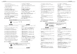
12.Checking operation:

a. Connect the AC cord to the MC-80.
b. Turn on the MC-80 power while holding down [CHAIN 

PLAY],[REC] and [ARPEGGIATOR] at the same time.

c. Insert a formatted ZIP disk into the ZIP drive after 

entering the test mode.

d. After pressing [F6(next)], MC-80 automatically executes 

the device checking.

e. The system properly operates, when the ZIP/HD icon is 

NOT displayed.
Make sure of the following, when the ZIP/HD icon is 
displayed.

IDE

-Check the wirings connected properly.

No Disk!

-Check the ZIP disk inserted into the formatted 

ZIP disk.

13.Executing the operation of shutdown.

a. While holding down the [SHIFT] button, press the [STOP] 

button.

b. When "The MC-80 may now be shut down safely" 

appears in the display, turn off the power.

* Return the removed ANGLE HD L/R (with 2 screws), MC-80 

IDE BOARD and excess 2 screws with the MC-80 to 
customer.

12.

動作チェックを行います。

a. MC-80 

の電源ケーブルを接続します。

b. [CHAIN PLAY]+[REC]+[ARPEGGIATOR]

を押しながら、

MC-80

の電源を投入します。

c.

テストモードに入ったら、フォーマット済みの

ZIP

ディ

スクを

ZIP

ドライブに挿入します。

d. [F6(NEXT)] 

を押しデバイスチェックを行います。

e. ZIP/HD

アイコンが表示されなければ、動作は OK で

す。

ZIP/HD

アイコンが表示された場合は、以下の点を

チェックしてください。

IDE -

ワイヤリングが正しく挿されているか?

No Disk!

-ZIP

ドライブに

 ZIP

ディスクが入っているか?

13.

シャットダウン操作を行います。

a. [SHIFT]

を押しながら、

[STOP]

を押します。

b. "The MC-80 may now be shut down safely"

と表示された

ら、電源を落としてください。

※ 取り外したアングル

HD-L/R

(ネジ2本付き)と

IDE

ボード

および余ったネジ2本は

 MC-80

とともにお客様に返却して

ください。

The Roland HDP88 Series HARD DISK DRIVE UNIT can be 
installed as the internal hard disk.

♦ 

♦ 

♦ 

♦ 

NOTICE:

When the internal ZIP drive unit (ZIP-INT-1A) has already been 
installed in customer’s MC-80, The parts listed below is 
required.
Be sure to take them back from customer.

As follows, re-install the parts listed above in the MC-80 before 
installing the internal hard disk drive unit.

a. Turn off the power for the MC-80 and any connected 

devices, and disconnect any cables connected to the 
MC-80.

b. Turn the MC-80 over, and remove the bottom cover.
c. Seeing page "INSTALLING THE INTERNAL ZIP DRIVE 

UNIT(ZIP-INT-1A)", remove the ZIP drive unit from 
step11 to step2 in reverse steps.

d. Re-attach the bottom cover.

* Return the ZIP drive unit with the MC-80 to customer.

ローランド

HDP88

シリーズのハードディスクを内蔵できます。


お読みください

お読みください

お読みください

お読みください

お客さまの

MC-80

に内蔵

ZIP

ドライブユニット

(ZIP-INT-1A)

が取り付けられている場合、以下の部品が必要になります。必
ずお客さまから回収してください。

内蔵ハードディスクドライブユニットを取り付ける前に上記の
部品を以下の手順で

MC-80

に取り付けておく必要があります。

a. MC-80

と接続している機器の電源を切り、

MC-80

に接続

されているすべてのケーブルを外します。

b. MC-80

を裏返し、ボトムカバーを外します。

c.

「内蔵

ZIP

ドライブユニット(

ZIP-INT-1A

)の取り付け

方法」を参照し、手順

11

から

3

へ、逆の手順で内蔵

ZIP

ドライブユニットを外してください。

d.

ボトムカバーを取り付けます。

※ なお取り外した内蔵

ZIP

ドライブユニットは、

MC-80

とと

もにお客様に返却してください。

Part No.

Part Name

quantity

71123145

IDE BOARD

1

00897812

ANGLE HD-R

1

00897823

ANGLE HD-L

1

40013067

DOUBLE SEMS (SMALL WASHER) 
M3x8 ZC

2

40011101

BINDING TAPTIGHT B 3x8MM BZC

2

部品番号

品目名称

数量

71123145

IDE BOARD ASSY

1

00897812

ANGLE HD-R

1

00897823

ANGLE HD-L

1

40013067

DOUBLE SEMS (SMALL WASHER) 
M3x8 ZC

2

40011101

BINDING TAPTIGHT B 3x8MM BZC

2

♦ 

♦ 

♦ 

♦ 

Procedure:

1. Turn off the power for the MC-80 and any connected 

devices, and disconnect any cables connected to the MC-
80.

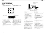
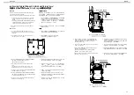
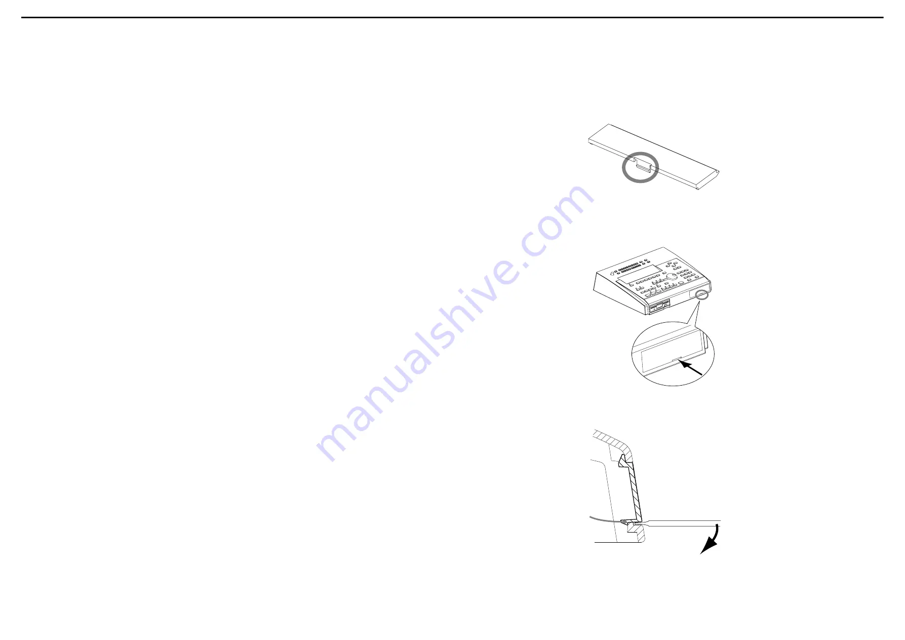
2. Remove the MC-80’s front cover.

The cover clasp latches onto the body to secure the cover.
(See fig.6)

◆手順

◆手順

◆手順

◆手順

1. MC-80

と接続している機器の電源を切り、

MC-80

に接続

されているすべてのケーブルを外します。

2. MC-80

のフロント・カバーを外します。

このカバーは爪部が本体ボディーにひっかかって固定され
ています。(

fig.6

参照)

fig.6

3. Wrap the tip of a flat head screwdriver with a cloth or 

similar material and insert it as shown in the figure.
Inserting the screwdriver directly without covering the tip 
can scratch the body.Always cover the tip first.(See fig.7)

3.

マイナスドライバーの先を布等で覆って図の位置に差し込
みます。
ドライバーを直接差し込むとボディーに傷がつきます。
必ず布をご用意ください。(

fig.7

参照)

fig.7

4. Gently push the screwdriver downwards to remove the 

cover.(See fig.8)

4.

ドライバーを軽く下方に押して、カバーを取り外します。

fig.8

参照)

fig.8

Содержание Micro Composer MC-80

Страница 1: ...created in a song 16 MIDI 1 6 16 MIDI 1 1 1 1 100 Song Data Internal Memory Songs 1 Note Capacities approx 120 000 notes Song Length 9 998 measures 1 120 000 9 9 9 8 Storage Media 3 5 inch Micro Flop...

Страница 2: ...358 303 88 mm Weight 3 3 kg 7 lbs 5 oz 3 3 kg Accessories MC 80 Owner s Manual English 71231123 Japanese 71121945 Demo Song Floppy Disk 01564556 Power Supply Cord 120V 00894378 230V 00894389 230VE 00...

Страница 3: ...3 Feb 1999 MC 80 LOCATION OF CONTROLS...

Страница 4: ...346045 FUJI CARD 35pin 35X110 A6 0BB P1 25 HBL10 40340045 CUSHION NW1030 1 6X60X40M 01782678 FERRITE CORE SSC 58 12 01780790 FUJI CARD 26pin 26X160 A6 0BB P1 25 HBL10 01459123 WIRING FDD POWER 0167309...

Страница 5: ...C 1 40011101 Binding Taptight B 3x8mm BZC 28 40011278 Binding Taptight P 3x8mm ZC 38 40011312 Binding Taptight P 3x8mm BZC 5 40238501 Binding Taptight P 4x8mm BZC 6 40340812 Sems 3x10mm BZC 4 40011501...

Страница 6: ...C 1 40011101 Binding Taptight B 3x8mm BZC 28 40011278 Binding Taptight P 3x8mm ZC 38 40011312 Binding Taptight P 3x8mm BZC 5 40238501 Binding Taptight P 4x8mm BZC 6 40340812 Sems 3x10mm BZC 4 40011501...

Страница 7: ...eb 1999 MC 80 WIRING DIAGRAM fig 1 fig 1 This arrangement of wirings apply to S N ZL50100 ZL50199 fig 1 ZL50100 ZL50199 fig 2 fig 2 This arrangement of wirings apply to S N ZL70200 or later fig 2 ZL70...

Страница 8: ...108 on JB 15289709 M51954BFP 600D IC RESET IC105 on JB TRANSISTOR 15129164 DTC114ESTP DIGITAL TORANSISTOR Q501 508 on PB 15309101 2SA1037K T146 QRS TRANSISTOR CHIP Q103 105 110 on JB 15309103 2SA1202Y...

Страница 9: ...011312 SCREW M3X8 BINDING P TITE FE BZC 40011501 SCREW M3X8 SEMS PAN HEAD FE BZC 40011889 EXTERNAL TOOTH WASHER M4 FECM 40012301 SCREW M4X8 BIND TAPTITE B FE ZC 40013067 SCREW M3X8 PAN SEMS FE ZC 4023...

Страница 10: ...de Disk Read WIRING FDD WIRING FDD POWER MC 80 JACK BOARD Required item MIDI cable 2HD and 2DD Floppy Disk Formatted Headphones RH 120 etc Monitor Speaker MA 12 etc 2 Foot Switches FS 5U etc and PCS 3...

Страница 11: ...r DRAM is defective Check IC3 IC5 IC2 on the MAIN BOARD CPU ROM PROGRAM ROM D RAM MAIN BOARD IC3 IC5 IC2 Install ZIP INT 1A or HDP 88 in the MC 80 ZIP INT 1A HDP 88 MC 80 Insert a formatted ZIP disk i...

Страница 12: ...NCODER TEST6 LCD ENCODER 1 Press ENTER to test appears on display 2 Press ENTER then check that all dots of display are turned off 3 Press ENTER again then check that all dots of display are turned on...

Страница 13: ...T 4 F5 TEST 5 F5 TEST 6 F5 TEST 7 F6 NEXT VE GSPro JACK BOARD IC101 IC102 IC103 IC130 VR BOARD MAIN BOARD JACK BOARD TEST 9 CLICK TEST 9 CLICK 1 A metronomic click will sound from internal speaker 2 C...

Страница 14: ...8 2 8 BLOCK DIAGRAM MIDI IN 1 MIDI IN 2 MIDI THRU MIDI OUT 1 MIDI OUT 2 FOOT SW CPU SH7021 DRAM 16Mbit IC3 IC2 FLASH ROM 8Mbit GATE ARRAY M60205 0601FP ENCODER SW LED PANEL SWITCH BOARD IC5 IC4 LCDC S...

Страница 15: ...5 6 6 6 6 7 7 7 7 8 8 8 8 9 9 9 9 1 0 1 0 1 0 1 0 1 1 1 1 1 1 1 1 1 2 1 2 1 2 1 2 1 3 1 3 1 3 1 3 1 4 1 4 1 4 1 4 1 5 1 5 1 5 1 5 1 6 1 6 1 6 1 6 1 7 1 7 1 7 1 7 1 8 1 8 1 8 1 8 1 9 1 9 1 9 1 9 2 0 2...

Страница 16: ...2 2 2 2 3 3 3 3 4 4 4 4 5 5 5 5 6 6 6 6 7 7 7 7 8 8 8 8 9 9 9 9 1 0 1 0 1 0 1 0 1 1 1 1 1 1 1 1 1 2 1 2 1 2 1 2 1 3 1 3 1 3 1 3 1 4 1 4 1 4 1 4 1 5 1 5 1 5 1 5 1 6 1 6 1 6 1 6 1 7 1 7 1 7 1 7 1 8 1 8...

Страница 17: ...3 3 4 4 4 4 5 5 5 5 6 6 6 6 7 7 7 7 8 8 8 8 9 9 9 9 1 0 1 0 1 0 1 0 1 1 1 1 1 1 1 1 1 2 1 2 1 2 1 2 1 3 1 3 1 3 1 3 1 4 1 4 1 4 1 4 1 5 1 5 1 5 1 5 1 6 1 6 1 6 1 6 1 7 1 7 1 7 1 7 1 8 1 8 1 8 1 8 1 9...

Страница 18: ...3 3 3 4 4 4 4 5 5 5 5 6 6 6 6 7 7 7 7 8 8 8 8 9 9 9 9 1 0 1 0 1 0 1 0 1 1 1 1 1 1 1 1 1 2 1 2 1 2 1 2 1 3 1 3 1 3 1 3 1 4 1 4 1 4 1 4 1 5 1 5 1 5 1 5 1 6 1 6 1 6 1 6 1 7 1 7 1 7 1 7 1 8 1 8 1 8 1 8 1...

Страница 19: ...10 RA2 10k 1 2 3 4 5 6 7 8 9 10 RA1 10k 1 2 3 4 5 6 7 8 9 10 RA3 10k 1 2 3 4 5 6 7 8 9 10 RA4 10k 1 2 3 4 5 6 7 8 9 10 C37 0 1 IC9C TC7W02F 8 4 C30 0 1 C31 0 1 CN3 52045 3545 1 1 2 2 3 3 4 4 5 5 6 6...

Страница 20: ...k C130 47P R169 100k R172 1k R170 100k R173 1k C157 0 01 C158 0 01 DA101 DCG010 TL 1 2 3 DA102 DCF010 TL 1 2 3 R154 10k R171 4 7k C159 100P IC106F HD74LS05FP 13 12 R164 4 7k R157 10k C152 0 1 R158 10k...

Страница 21: ...00 1 8 2 7 3 6 4 5 RA111 100 1 8 2 7 3 6 4 5 RA121 100 1 8 2 7 3 6 4 5 IC117B TC7W04F 3 5 IC117A TC7W04F 1 7 RA115 1k 1 8 2 7 3 6 4 5 RA110 10k 1 2 3 4 5 6 7 8 9 10 RA112 10k 1 2 3 4 5 6 7 8 9 10 C212...

Страница 22: ...28 1 2 SW532 1 2 SW538 1 2 SW544 1 2 SW509 1 2 SW531 1 2 SW508 1 2 SW521 1 2 SW507 1 2 SW515 1 2 SW530 1 2 SW529 1 2 SW541 1 2 SW533 1 2 Q501 DTC114ES 3 1 2 C502 0 1 C501 0 1 Q502 DTC114ES 3 1 2 Q503...

Страница 23: ...202K 1 2 3 DA308 DAN202K 1 2 3 DA306 DAN202K 1 2 3 DA307 DAN202K 1 2 3 DA311 DAN202K1 2 3 DA310 DAN202K1 2 3 DA309 DAN202K1 2 3 DA301 DAN202K 1 2 3 DA302 DAN202K 1 2 3 DA303 DAN202K 1 2 3 SW314 1 2 4...

Страница 24: ...all the supplied core and fuji card CN108 8 Re attach the bottom cover 9 Checking operation a Prepare an external ZIP drive a 25pin SCSI cable and a formatted ZIP disk b Connect the external ZIP drive...

Страница 25: ...onnecting the MC 80 IDE BOARD and the ANGLE HD L R See fig 4 d 6 Remove the WIRING IDE and the WIRING IDE POWER from the MC 80 IDE BOARD s connectors CN401 CN402 on the DD HOLDER See fig 4 e 7 Remove...

Страница 26: ...take them back from customer As follows re install the parts listed above in the MC 80 before installing the internal hard disk drive unit a Turn off the power for the MC 80 and any connected devices...

Страница 27: ...alize the hard disk Connect the AC Cord and turn on the MC 80 power a Press TOOLS b Press F5 DISKUTIL c Press F6 MENU to select DISK MENU d Press F4 FORMAT e Press F1 DRIVE several times to select the...

Отзывы: