


21
3 Replacement of Main Parts
3
1
2
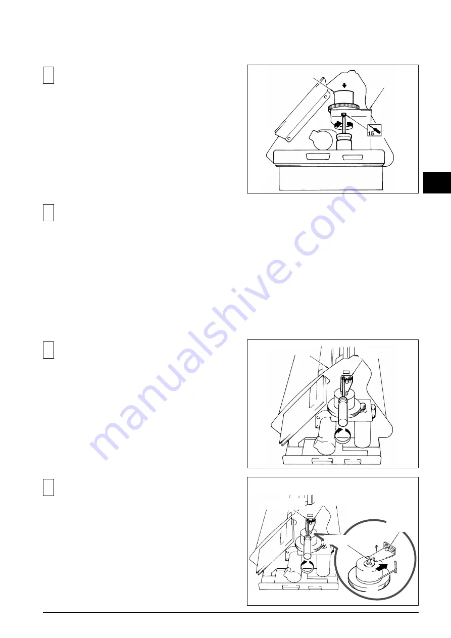
Fix the CARRIAGE MOTOR by checking the backlash.
3
Fix the SHAFT STAY temporary to the FRAME R.
4
Tighten the SCREW A for the SHAFT STAY until the
PULLEY SHAFT makes contact with the SHAFT STAY.
Tighten the SCREWS B.
Fix the CARRIAGE WIRE to the DRIVE PULLEY
ASSEMBLY (Page 22).
Fix the DRIVE PULLEY ASSEMBLY to the MOTOR BASE.
3-2 DRIVE PULLEY ASSEMBLY_FIXING
DRIVE PULLEY ASSEMBLY
SHAFT STAY
MOTOR BASE
FRAME R
SHAFT STAY
SCREW B
PULLEY SHAFT
SCREW A
Содержание CAMM-1 Pro PNC- 1410
Страница 49: ...47 5 Supplemental Information 5 5 1 OPERATIONAL SEQUENCE 5 Supplemental Information...
Страница 60: ......
Страница 61: ...PNC 1860 1410 1210...