background image

Operation

Operating the System

76

VENICE S | User Manual | 2906.1345.02 - 02

Rohde & Schwarz GmbH & Co. KG

3.

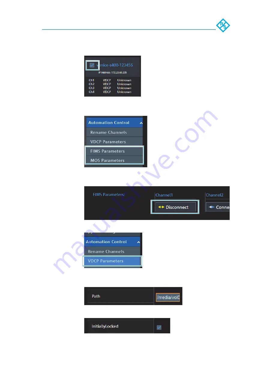
Select the respective system.

4.

If the system runs in another mode than VDCP select the 
running mode (e.g. FIMS).

5.

Click 

Disconnect

 to make the channel available for the 

VDCP mode.

6.

Select the 

VDCP

 mode 

in the 

Automation Control

 settings

.

7.

Enter a valid 

Path

 to a local or a central storage for each 

channel.

8.

Activate 

InitiallyLocked

 for each channel.

Содержание VENICE S

Страница 1: ...R S VENICE S User Manual 2906 1345 02 02 User Manual Broadcast and Media ...

Страница 2: ...GmbH Co KG 2018 Rohde Schwarz GmbH Co KG Hanomaghof 1 30449 Hanover Germany Phone 49 511 67807 0 Fax 49 511 67807200 Email support media rohde schwarz com Internet https www rohde schwarz com Subject to change Data without tolerance limits is not binding ...

Страница 3: ...flow based Metadata 17 Audio Routing 25 Image Processing 25 Timecode 26 Play After Write 27 Type Plate 28 Scope of Delivery 29 The Front of the System 30 Front Plate 30 Chassis Front 31 LCD Panel 32 Hard Drives 35 The Rear of the System 38 Back Panel 38 LTC In Out 40 AES EBU Audio 40 Power Supply Unit 41 Power Supply Indicator 42 Out or Input of Master Slave Control Signals 43 Downconvert Video Ou...

Страница 4: ...System 62 Starting the System 66 Configuring the System 67 Log In 67 Network Configuration 67 Integrating Software Service 68 System Update 68 Shutting Down the System 69 Operation 71 Operating the System 72 Usable Software and Protocols 72 VENICE Client Software 72 Playing Content 73 Ingesting Content 74 Transforming Content 74 File Management 74 Multi Viewing Content 75 Control VENICE S 75 Admin...

Страница 5: ... 103 Replacing a Cooling Fan 104 Replacing the Internal USB Memory Key 107 Transport 109 Safety Notes 110 Packing the System 111 Troubleshooting 113 Safety First For you and your System 114 Troubleshooting External Connections 115 Troubleshooting the Video Subsystem 116 Troubleshooting a USB Device 117 Troubleshooting a Wet System 118 Troubleshooting Power Supply Units 119 Troubleshooting Power So...

Страница 6: ...6 VENICE S User Manual 2906 1345 02 02 Rohde Schwarz GmbH Co KG ...

Страница 7: ...General 7 VENICE S User Manual 2906 1345 02 02 Rohde Schwarz GmbH Co KG General This chapter includes the following section About this Documentation page 8 ...

Страница 8: ...get Group To use this manual you should have experience in handling video and computer equipment When performing maintenance tasks on the hardware you must be qualified to work on repair and test electrical equip ment Additional Documentation Following documents have to be heeded while working with VENICE S Getting Started With Your System Data Sheet Safety Environment and Regulatory Information S...

Страница 9: ...Safety 9 VENICE S User Manual 2906 1345 02 02 Rohde Schwarz GmbH Co KG Safety This chapter is divided into the following sections For your Safety page 10 General Notes page 11 ...

Страница 10: ... data sheet Safety information is part of the product documentation It warns you about the potential dangers and gives instructions how to prevent personal injury or damage caused by dangerous situa tions Safety information is provided as follows In the Basic Safety Instructions safety issues are grouped according to subjects Throughout the documentation safety instructions are provided when you m...

Страница 11: ...figuring VENICE S anew in most cases is a lengthy procedure Modi fications of settings i e BIOS settings shall be done with Rohde Schwarz Third party Software VENICE is built for the most demanding realtime operations Third party software might have unpredictable influences to the overall performanc and stability of the system Do not install any third party software that has not been tested and ap...

Страница 12: ...Safety General Notes 12 VENICE S User Manual 2906 1345 02 02 Rohde Schwarz GmbH Co KG ...

Страница 13: ...t Description This chapter is divided into the following sections Function page 14 Models page 15 Features page 16 Type Plate page 28 Scope of Delivery page 29 The Front of the System page 30 The Rear of the System page 38 Inside the System page 49 Pin Assignment page 53 Network Ports page 60 ...

Страница 14: ...ICE web service or the R S Device Manager In ingest mode VENICE S assumes the role of a recorder For a remote controlled ingest set VENICE S in FIMS or VDCP mode via VENICE web service or the R S Device Manager In transform mode VENICE S transforms video and audio mate rial to different file formats If possible the file conversion transcoding will be performed in hardware at a faster render speed ...

Страница 15: ...s 15 VENICE S User Manual 2906 1345 02 02 Rohde Schwarz GmbH Co KG Models The following models are available VENICE S400 no internal media storage VENICE S407 7 TB internal media storage VENICE S414 14TB internal media storage ...

Страница 16: ... has proven itself a thousand times over in data centers worldwide Comprehensive software based codec support VENICE S minimizes the need for transcoding by supporting a variety of software based codecs that can be expanded via future software updates Service oriented architecture FIMS and web services communications allow the greatest possible interoperability flexibility and integrability in the...

Страница 17: ...anking interval information VBI information will be converted to ANC on any output raster INPUT OUTPUT ANC VBI Closed Caption PLAYOUT ANC Closed Caption SD SDI V Lines 525 VBI CEA 608 data ANC CEA 608 data ANC VBI CEA 608 data1 SD SDI V Lines 625 ANC CEA 608 data SMPTE 334 1 HD SDI ANC Closed captioning CEA 708 CDP SMPTE 334 1 HD SDI ANC Closed captioning CEA 708 CDP ANC CEA 608 data SD SDI V Line...

Страница 18: ...bedded closed caption information stored in QuickTime MOV It records embedded CEA 708 information from the incoming SDI signal in digital SD and HD When writing QuickTime files ingest or transform the closed caption data are preserved in the following order whereas the first type found is written into the files 1 CEA 708 ANC digital 2 CEA 608 ANC digital By default it is a QuickTime CEA 708 track ...

Страница 19: ...f more tracks will be necessary closed caption information also can be written in a separate scc file For this additional scc 3 files have to be enabled in the video settings of the R S Device Manager Field 2 of a video frame then transfer closed caption tracks three and four For playout purposes external scc files can be inserted to the SDI signal Subtitles VENICE S allows pass through of embedde...

Страница 20: ...n with it Outside the US WSS Wide Screen Signaling was sometimes used with SD signals to define the aspect ratio The information was stored on VBI line 20 for NTSC and line 23 for PAL Meanwhile AFD has replaced WSS for both SD and HD material AFD Active Format Description describes the video picture in terms of the aspect ratio and other characteristics of the active image within the coded frame W...

Страница 21: ...ull frame 16 9 image the same as the coded frame 0011 Letterbox 14 9 image at the top of the coded frame 1011 Pillarbox 14 9 image horizontally centered in the coded frame 0100 Letterbox image with an aspect ratio greater than 16 9 vertically centered in the coded frame 0100 Letterbox image with an aspect ratio greater than 16 9 vertically centered in the coded frame 0101 Reserved Invalid 0110 Res...

Страница 22: ... 9 image vertically centered in the coded frame 0100 Letterbox image with an aspect ratio greater than 16 9 vertically centered in the coded frame 0100 Letterbox image with an aspect ratio greater than 16 9 verti cally centered in the coded frame 0101 Reserved Invalid 0110 Reserved Invalid 0111 Reserved Invalid 1000 Full frame 16 9 image the same as the coded frame 1010 Letterbox 16 9 image vertic...

Страница 23: ...native 14 9 center 1101 Full frame 4 3 image with alternative 14 9 center 1110 Full frame 16 9 image with alternative 14 9 center 1110 Letterbox 16 9 image with alternative 14 9 center 1111 Full frame 16 9 image with alternative 4 3 center 1111 Letterbox 16 9 image with alternative 4 3 center AFD In Input 4 3 AFD Out Output 16 9 ...

Страница 24: ...deo material are different Therefor the following parameter are available AFD 1010 AR 16 9 AFD 1001 AR 16 9 AFD 1000 or 1010 AR 16 9 AFD 1011 AR 16 9 AFD 1000 or 1010 AR 16 9 AFD 1001 AR 16 9 AFD 1000 or 1010 AR 16 9 AFD 1011 AR 16 9 AFD 1111 AR 16 9 AFD 1010 AR 4 3 AFD 1000 or 1001 AR 4 3 AFD 1000 or 1010 AR 16 9 AFD 1011 AR 4 3 AFD 1010 AR 4 3 AFD 1001 AR 4 3 AFD 1000 or 1010 AR 16 9 AFD 1011 AR...

Страница 25: ...e Processing Off The material will maintain its original size Box The aspect ratio will not be preserved The resulting images will be stretched or compressed if the aspect ratio is different and you will always receive a full image in the output Crop The images will be scaled to their maximum allow able width or height so that you receive a full image at the output If the aspect ratio is different...

Страница 26: ...rval Timecode VTRTC RS 422 Timecode DVITC Digital Vertical Interval Timecode DLTC Digital Longitudinal Timecode Time of day OUTPUT 480i29 97 576i25 720p50 720p59 94 1080p25 1080p 9 97 1080i25 1080p50 1080i29 97 1080p59 94 2160p50 2160p59 94 INPUT 480i29 97 x x 576i25 x x 720p50 x x x x 720p59 94 x x x x 1080p25 x x x x 1080p29 97 x x x x x 1080i25 x x 1080p50 x x x x 1080i29 97 x x 1080p59 94 x x ...

Страница 27: ...e video image DVITC replaces the previously used VITC of analog systems DVITC will be recorded most preferably in line 9 and 10 of the SDI signal at the output of MAZ devices VTRTC RS 422 is a via RS 422 transferred timecode of a controlled video source Time of day is the actual time of the device Play After Write The automated play after write functionality allows a true visual quality check It r...

Страница 28: ...Product Description Type Plate 28 VENICE S User Manual 2906 1345 02 02 Rohde Schwarz GmbH Co KG Type Plate Type plate 1 Type 2 Article number 3 Serial number 4 Product description 2 1 2 3 4 ...

Страница 29: ... Cable management kit Power cable rack 2x SR SFP 10GbE optical transceiver SDI 3G SFP bundle 4x SDI 3G combined input and output SFPs for 4 bidirectional HD SDI channels includes 2x 3G dual receiver and 2x 3G dual transmitter Product documentation Optional VENICE accessory kit 8x HD BNC to BNC adapter cables 4x RJ45 to DB9 adapter cables RS422 1x HD D SUB 26 male to 8 x XLR female male breakout ca...

Страница 30: ...hde Schwarz GmbH Co KG The Front of the System Front Plate The front plate covers all operation items and the disk array It is attached on mounting on the left and on the right side in the front For more information see chapter Removing and Mounting the Front Plate on page 92 Front plate ...

Страница 31: ...stem 2 NMI button Enables you to troubleshoot software and device driver errors when running certain operating systems This button can be pressed by using the end of a paper clip 3 System iden tification button Enables you to locate a particular system within a rack The identification buttons are located on the front and back panels Press the system identification button to turn the system ID on o...

Страница 32: ...ght button on the LCD panel The LCD backlight remains off if LCD messaging is turned off using the iDRAC utility the LCD panel or other tools 6 Information tag Contains system information such as service tag NIC MAC address for your reference The infor mation tag is a slide out label panel 7 LCD panel Displays system ID status information and system error messages The LCD turns blue during normal ...

Страница 33: ...ight 2 To navigate to the home screen from another menu complete the following steps Press and hold the up arrow until the Home icon is displayed Select the Home icon On the home screen press the Select button to enter the main menu Setup Menu 1 Left Moves the cursor back in one step increments 2 Select Selects the menu item highlighted by the cursor 3 Right Moves the cursor forward in one step in...

Страница 34: ...screen See chapter View Menu on page 34 or the options and option items that can be set as the default on the home screen When you select an option in the VIEW menu you must confirm the option before proceeding to the next action iDRAC IP Displays the IPv4 or IPv6 addresses for iDRAC Addresses include DNS Primary and Secondary Gateway IP and Subnet IPv6 does not have Subnet MAC Displays the MAC ad...

Страница 35: ...Manual 2906 1345 02 02 Rohde Schwarz GmbH Co KG Hard Drives Hard drives For more information about removing and installing a hard drive see chapter Replacing a Hot Swappable Hard Drive on page 100 1 Release button 2 Hard drive carrier 3 Hard drive carrier handle ...

Страница 36: ...mode the status indicator on the right side does not function and remains off Flashes green twice per second Identifying drive or preparing for removal Off Drive ready for insertion or removal NOTE The drive status indicator remains off until all hard drives are initialized after the system is turned on Drives are not ready for insertion or removal during this time Flashes green amber and turns of...

Страница 37: ...n The Front of the System 37 VENICE S User Manual 2906 1345 02 02 Rohde Schwarz GmbH Co KG Steady green Drive online Flashes green for three seconds amber for three seconds and turns off after six seconds Rebuild stopped ...

Страница 38: ... one of the buttons is pressed again Press to toggle the system identifi cation ID on or off 2 System identi fication connector Connects the optional system status indicator assembly through the optional cable management kit 3 iDRAC Enter prise port Dedicated management port 4 Half height PCIe expan sion card slot 3 Enables you to connect up to three half height PCI Express expansion cards 5 Seria...

Страница 39: ...erial RS 422 interface 4 Out or input of master slave control signals For more information see Out or Input of Master Slave Control Signals on page 43 and for the pin assignment chapter RJ45 Connector on page 54 12 HD BNC connector Downconvert video output For more information see chapter Downconvert Video Output on page 43 13 SFP port 4 In Output of digital video signals For more information see ...

Страница 40: ... VENICE S gives you the possibility to use LTC timecode on each channel for ingest and playout Receive or provide LTC timecode with the supplied Lynx cable see chapter Lynx CBL AES1604 Cable on page 58 Via the R S Device Manager it s possible to assign LTC time code that is received by one channel to all other channels AES EBU Audio HD Sub D connectors optional 1 Channel 1 2 Channel 2 3 Channel 3 ...

Страница 41: ...mbH Co KG Power Supply Unit Your system supports two 750 W multi range PSUs 90 240 VAC Power supply unit For more information about removing and installing a PSU see chapter Replacing a Power Supply Unit on page 97 1 Release latch 2 Power supply status indicator 3 PSU 4 Power connector 5 PSU handle ...

Страница 42: ...Indicator Codes PSU status indicator codes 1 PSU status indicator handle 2 Status Condition A Green A valid power source is connected to the PSU and the PSU is operational B Flashing green When the firmware of the PSU is being updated the PSU handle flashes green C Flashing green and turns off When hot adding a PSU the PSU handle flashes green five times at 4 Hz rate and turns off This indicates a...

Страница 43: ...E S is slave With software version 3 5 it is possible to change between master and slave in the R S VENICE Client software Downconvert Video Output HD BNC connector The downconvert video output can be used for HD monitoring while the system is configured for UHD operation The down convert functionality is only active with UHD or 4K rasters If enabled the UHD material will be send via the SDI outpu...

Страница 44: ...e will be converted to a single field in alter nating order All original motion phases will be kept during this conversion Due to the enormous scaling factor from SD to UHD this conversion might incooperate aliasing 2 This conversion skips every second original frame resulting in a reduction of temporal resolution Compared to the UHD output the downconvert output ist delayed by a number of frames ...

Страница 45: ... or 3G video signals To use the functionality you have to insert the dual receiver and the dual transmitter into the SFP ports For more information see chapter Installing the System on page 62 3GB SDI SFP coxial dual transmitter 3G SDI SFP coxial dual receiver Default Channel Assignment The following modes are available Single link mode HD Use only original Rohde Schwarz certified parts 1 3 1 3 2 ...

Страница 46: ... S Device Manager Video I O Formats SDI 270 Mb s Single Link SDI 1 5G Single Link SDI In SDI Out A C B D A C B D Standard Raster Framerate Cabling per channel SMPTE 259M 525i 29 97 fps 1x SDI 1 5G SMPTE 259M 625i 25 fps Standard Raster Framerate Cabling per channel SMPTE 274M 1080i 1080p 1080PsF 25 fps 29 97 fps 1x SDI 1 5G SMPTE 296M 720p 25fps 29 97fps 50fps 59 94fps ...

Страница 47: ...nectors Standard Raster Framerate Cabling per channel SMPTE 425 1080p 50fps 59 94fps 1x SDI 3G Standard Raster Framerate Cabling per channel SMPTE 2036 2160p 25fps 29 97fps 4x SDI 1 5G Standard Raster Framerate Cabling per channel SMPTE 2036 2160p 50fps 59 94fps 4x SDI 3G Port Configuration Speed 1 eno1 unconfigured 10 Gbps SFP 2 eno2 unconfigured 10 Gbps SFP 3 eno3 DHCP 1 Gbps RJ45 4 eno4 static ...

Страница 48: ...vity indicator 2 Status Condition A Link and activity indicators are off The NIC is not connected to the network B Link indicator is green The NIC is connected to a valid network at its maximum port speed 1 Gbps or 10 Gbps C Link indicator is amber The NIC is connected to a valid network at less than its maximum port speed D Activity indicator is flashing green Network data is being sent or receiv...

Страница 49: ...move the system cover System Cover The system cover protects the components inside the system Removing the system cover actuates the intrusion switch which aids in maintaining system security System cover For more information about opening and closing the system cover see chapter Removing the System Cover on page 94 and chapter Installing the System Cover on page 95 1 System cover 2 Latch 3 Latch ...

Страница 50: ...uch as the processors hard drives and memory get adequate air circulation to keep them cool A failure in the server s cooling system can result in the server overheating and may lead to damage For more information about removing and installing the cooling fan assembly see chapter Replacing a Cooling Fan Assembly on page 103 1 Cooling fan assembly 2 Cooling fan 6 3 Release lever 2 4 Guide pin on th...

Страница 51: ... installing a cooling fan see chapter Replacing a Cooling Fan on page 104 1 Cooling fan assembly 2 Cooling fan connector 6 3 Fan release tab 6 4 Cooling fan 6 5 Cooling fan connector on the system board 6 In the event of a problem with a particular fan the fan number is referenced by the R S Device Manager al lowing you to easily identify and replace the proper fan by noting the fan numbers on the...

Страница 52: ... The VENICE contains an internal USB flash drive that can be used to restore the operating system on the system disk back to its manufacturing state Further information you will find in chapter Replacing the Internal USB Memory Key on page 107 chapter Creating a Backup Image on page 80 and chapter Restoring the System on page 83 ...

Страница 53: ...on page 40 and information about the cable available in chapter Lynx CBL AES1604 Cable on page 58 HD Sub D connector external view on device female Pin No Signal Pin No Signal 1 GROUND 14 OUT1 N 2 OUT4 N 15 IN4 P 3 GROUND 16 IN3 N 4 OUT2 N 17 IN2 P 5 GROUND 18 IN1 N 6 IN4 N 19 GROUND 7 GROUND 20 OUT3 P 8 IN2 N 21 GROUND 9 GROUND 22 OUT1 P 10 WORDCLOCK OUT 23 GROUND 11 OUT4 P 24 IN3 P 12 OUT3 N 25 ...

Страница 54: ...r serial RS 422 interface 4 external view on device female RJ45 Slave Mode default Master Mode Pin No Signal Signal 1 GND GND 2 reserved reserved 3 RX TX 4 TX RX 5 TX RX 6 RX TX 7 not connected not connected 8 not connected not connected If you want to manufacture a direct line VDCP cable please note the slave mode assignment above Your VDCP cable should connect the automation s TX pins with the R...

Страница 55: ...1345 02 02 Rohde Schwarz GmbH Co KG Serial Connector The COM port enables you to connect a serial device to the system R232 connector external view on device female Pin No Signal Pin No Signal 1 DCD 6 DSR 2 RXD 7 RTS 3 TXD 8 CTS 4 DTR 9 RI 5 Ground 1 2 3 4 5 6 7 8 9 ...

Страница 56: ...or external view on device female Adapter Cable With the adapter cable its possible to transfer the master slave control signal For more information see chapter RJ45 Connector on page 54 RS 422 RJ 45 RIB7 0 male to D Sub 9 Pin No Signal Pin No Signal 1 RED 9 KEY 2 GREEN 10 SGND 3 BLUE 11 ID0 4 ID2 12 ID1 or SDA 5 GND 13 HSYNC or CSYNC 6 RGND 14 VSYNC 7 GGND 15 ID3 or SCL 8 BGND 5 10 6 1 15 11 ...

Страница 57: ...z GmbH Co KG RS 422 RJ45 RIB7 0 male to D Sub 9 female external view RJ45 Slave Mode default Master Mode D Sub 9 Pin No Signal Signal Pin No 1 GND GND 4 6 2 reserved reserved 5 3 RX TX 3 4 TX RX 2 5 TX RX 7 6 RX TX 8 7 8 not connected not connected 1 9 5 4 3 2 1 D Sub 9 RJ 45 9 8 7 6 1 8 ...

Страница 58: ...er an LTC in and output signal for each channel For more information see chapter LTC In Out on page 40 Lynx CBL AES1604 cable Lynx CBL AES1604 cable external view Pin No Signal Pin No Signal 1 GROUND 14 OUT1 N 2 OUT4 N 15 IN4 P 3 GROUND 16 IN3 N 4 OUT2 N 17 IN2 P 5 GROUND 18 IN1 N 6 IN4 N 19 GROUND 7 GROUND 20 OUT3 P 8 IN2 N 21 GROUND 9 GROUND 22 OUT1 P 19 10 1 26 18 9 ...

Страница 59: ...ct Description Pin Assignment 59 VENICE S User Manual 2906 1345 02 02 Rohde Schwarz GmbH Co KG 10 WORDCLOCK OUT 23 GROUND 11 OUT4 P 24 IN3 P 12 OUT3 N 25 GROUND 13 OUT2 P 26 IN1 P Pin No Signal Pin No Signal ...

Страница 60: ...nfo Multicast Maintenance Automation Software VENICE View VENICE Play VENICE Control Spycer 3702 UDP WSDD service discovery x x x x 3000 TCP Device Manager x 8031 TCP Installation service RSI x 8070 TCP Maintenance service x 811 TCP VDCP over IP x 471 TCP Video overlay streaming x x 30002 40001 TCP SpycerNet x x x 801 TCP VENICE web service X channel x x x 30001 UDP SpycerNet service discovery x x...

Страница 61: ...anual 2906 1345 02 02 Rohde Schwarz GmbH Co KG Installation and Configuration This chapter is divided into the following sections Installing the System page 62 Starting the System page 66 Configuring the System page 67 Shutting Down the System page 69 ...

Страница 62: ...hin reach of a power outlet or mount it in a rack For proper air circulation and cooling make sure the ventilation holes on the rear of the system are not covered Warranty Claims To make warranty claims you have to keep the original packing and use it in case of a return transportation Risk of Injury Improper handling of the VENICE S can cause substantial damage to personnel and equipment by falli...

Страница 63: ... conditions Do not expose VENICE S to sources of heat such as direct sunlight or a radiator Do not cover or obstruct the ventilation holes of the system When installing the system in a rack take care that warmed up air is conducted to the rear of the rack and properly vented away Avoid areas with high humidity or dust Best operating conditions are given in an air condi tioned site Do not expose VE...

Страница 64: ...nnect the system to a power source 6 Loop and secure the power cable using the retention strap 7 Connect a network cable to the Ethernet connector eno3 The IP address is assigned automatically 8 Connect a network cable to the Ethernet connector eno4 The default IP is 10 0 0 8 Use only original Rohde Schwarz certified parts ...

Страница 65: ...l receiver as shown in the following in the according SPF port 10 Connect the HD BNC to BNC adapter cables to the SDI In Out connectors 11 Connect any other peripheral computer and video equip ment An overview of the panels and connectors are listed in chapter The Rear of the System on page 38 VENICE S is ready for first use The VENICE S hardware is now properly installed and you can switch on the...

Страница 66: ...tch briefly to turn on the system The system will be started It takes several minutes until the system is fully operational For the initial setup the device must be integrated into a network If the IP of the device is already known a remote SSH terminal e g Putty can be used to make the basic configura tion Alternatively a monitor and keyboard can be temporarily connected on the front or on the re...

Страница 67: ...password password Network Configuration There are two ways for the network configuration You can use a dynamic or a static IP address as described bellow Dynamic IP Perform the following steps Determine the dynamic IP with the command ifconfig eno3 Static IP Perform the following steps 1 Edit the configuration file with vi etc sysconfig network scripts ifcfg eno4 2 Change line IPADDR 10 0 0 8 into...

Страница 68: ...red to use the interface eno3 Only use the following steps if a different configuration is necessary Perform the following steps Use the command fbms setup c interface to inte grate the software services on the network e g fbms setup c eno4 After the command is executed the configuration is complete VENICE S can immediately be operated by remote control from any Windows system connected to the sam...

Страница 69: ...ings and once it has ended the system will turn off System is shut down Shut Down With Operating System Frozen or Not Completely Loaded If the operating system is not responding anymore or not completely loaded do as follows Perform the following steps Shut down the system by pressing the power switch lengthly until the system turns off The system is shut down Re start It takes a while to safely e...

Страница 70: ...Installation and Configuration Shutting Down the System 70 VENICE S User Manual 2906 1345 02 02 Rohde Schwarz GmbH Co KG ...

Страница 71: ...Operation 71 VENICE S User Manual 2906 1345 02 02 Rohde Schwarz GmbH Co KG Operation This chapter includes the following section Operating the System ...

Страница 72: ... and Protocols VENICE Client Software Software Version 3 5 Software Version 4 Ingest R S VENICE Client VDCP RS 422 TCP IP R S VENICE Control R S VENICE Control FIMS capture SOAP FIMS capture SOAP Playout R S VENICE Client VDCP RS 422 TCP IP R S VENICE Play R S VENICE Play MOS SOAP MOS SOAP Transform R S VENICE Client FIMS transform SOAP FIMS transform SOAP Usable only with software version 3 5 ...

Страница 73: ...NICE servers at the same time In addition VENICE S supports MOS 3 8 4 using SOAP By embracing and implementing MOS Rohde Schwarz has opened and simplified the integration of the VENICE S Furthermore VENICE S with software version 4 is VDCP compliant This proprietary communications protocol primarily is used in broadcast automation to control broadcast devices like video servers for broadcast telev...

Страница 74: ...or more information see chapter Control VENICE S on page 75 Transforming Content With software version 3 5 it is possible to control transform jobs with the R S VENICE Client software as well as via FIMS With software version 4 you must use FIMS for this function ality For more information see chapter Control VENICE S on page 75 File Management The innovative data and content control software R S ...

Страница 75: ... need of extra SDI cabling and expensive multi viewer equipment Control VENICE S To use one of the mentioned methods on a VENICE S with soft ware version 4 activate the respective function in the R S Device Manager For more information about the different web services VDCP as well as how to integrate and control VENICE S by third party software see the Software Integration Guide available at https...

Страница 76: ...stem 4 If the system runs in another mode than VDCP select the running mode e g FIMS 5 Click Disconnect to make the channel available for the VDCP mode 6 Select the VDCP mode in the Automation Control settings 7 Enter a valid Path to a local or a central storage for each channel 8 Activate InitiallyLocked for each channel ...

Страница 77: ...ctive channel A successfully started connection of a channel in VDCP mode will be indicated in the system view Video Settings Perform the following steps 1 Select the Sync Reference settings in the Video Settings 2 Set the Sync Mode the syncHPhase and the syncVPhase as needed For detailed information see the documentation of the R S Device Manager ...

Страница 78: ...he System 78 VENICE S User Manual 2906 1345 02 02 Rohde Schwarz GmbH Co KG 3 Select the HD UHD settings in the Video Settings 4 Set the Mode as needed For detailed information see the documentation of the R S Device Manager ...

Страница 79: ...User Manual 2906 1345 02 02 Rohde Schwarz GmbH Co KG Administration This chapter is divided into the following sections Creating a Backup Image page 80 Restoring the System page 83 System Update page 86 System Monitoring page 87 ...

Страница 80: ...1 If appropriate disconnect all externally connected storage devices from the system 2 Turn on the VENICE S At the indicated moment during start up you have to press F11 to enter the boot menu The boot menu is displayed on the screen 3 Select the internally installed USB flash drive as the boot device 4 Press Enter The system will boot from the internal USB flash drive You will see a window on the...

Страница 81: ...ent some user entries are required For this follow the instructions given on the screen The loading of the environment and the process itself will both try to initialize hardware that may not be pres ent on your system Any error messages displayed during loading initialization e g Failed or Warning can be disregarded The backup recovery process should work nonetheless If you do not perform any act...

Страница 82: ...The program starts the backup process Its progress will be indicated on the screen When the system has finished the backup process you will be notified about this Then after pressing Enter you will be redi rected to the Rohde Schwarz Rescue script once more where you can choose for example reboot or poweroff to restart or turn off the system Data Loss Selecting the wrong source device may lead to ...

Страница 83: ...B flash drive You will see a window on the screen where you can select the Rohde Schwarz Rescue environment for loading 5 Select RuS Rescue and press Enter Total Loss of Data Selecting the wrong device for restoring the system partition will lead to a total loss of data Do not execute any commands if you are not sure about the correct target device To complete the loading of the Rohde Schwarz Res ...

Страница 84: ...s device name e g 1 0 0 0 disk ATA device info dev sda If you do not perform any action RuS Rescue will be loaded automatically after 30 seconds Ex factory the VENICE S will be delivered with sda as the default system disk If other configura tions have been made later or on customer re quest this may be different Data Loss A recovery will overwrite all your data Continue with the following steps o...

Страница 85: ...ection and whether you want to continue 9 To start the recovery process type in y for yes and press Enter The program starts the recovery process Its progress will be indicated on the screen When the system has finished the recovery process you will be notified Then after pressing Enter you will be redirected to the RuS Rescue script once more where you can choose for example reboot or poweroff to...

Страница 86: ... The installation routine starts and will guide you through the installation process 6 Follow the instructions given on the screen During the installation procedure all necessary files and libraries will be installed on the computer system The installation will be finished as soon as a message reports this 7 Shut down the server with the command poweroff 8 Restart the server by pressing the power ...

Страница 87: ...il noti fication as well The following parts can be queried Fans Disks arrays Power supply units CPU SNMP The Simple Network Management Protocol SNMP is a stan dard internet protocol for the device management in IP networks SNMP allows you to e g monitor and query the state of several VENICE devices in a network or single parts of the hardware VENICE S provides a StorageManagement MIB and MIB Dell...

Страница 88: ... System Board Inlet Temp Temperature in C 10 the value needs to be devided by 10 e g reading 220 22 C 1 3 6 1 4 1 674 108 92 1 700 20 1 6 1 2 System Board Exhaust Temp 1 3 6 1 4 1 674 108 92 1 700 20 1 6 1 3 CPU1 Temp 1 3 6 1 4 1 674 108 92 1 600 12 1 5 1 1 PS1 Status other 1 unknown 2 ok 3 nonCrit ical 4 critical 5 nonRecoverable 6 1 3 6 1 4 1 674 108 92 1 600 12 1 5 1 2 PS2 Status Storage Manage...

Страница 89: ...ections Safety Instructions page 90 Removing and Mounting the Front Plate page 92 Removing and Mounting the System Cover page 94 Replacing a Power Supply Unit page 97 Replacing a Hot Swappable Hard Drive page 100 Replacing a Cooling Fan Assembly page 103 Replacing a Cooling Fan page 104 Replacing the Internal USB Memory Key page 107 ...

Страница 90: ... the system while the system is powered on System Damage Operating the system without the system cover can result in component damage Do not operate the system without the cover for a duration exceeding five minutes Warranty Claims Many repairs may only be done by a certi fied service technician You should only perform troubleshooting and simple repairs as authorized in your product documentation ...

Страница 91: ... measures they can be destroyed Use a wrist strap connected to ground when accessing electronic parts and take care of grounding the system Avoid touching the internal components of the computer system and the video board whenever possible Proper Operation and Cooling To ensure proper operation and cooling all bays in the system and system fans must be populated always with either a component or a...

Страница 92: ...al 2906 1345 02 02 Rohde Schwarz GmbH Co KG Removing and Mounting the Front Plate Removing the Front Plate Perform the following steps 1 First remove the front plate on the right side from the front 2 Remove the front plate from the mountings on the left side of the front ...

Страница 93: ...e 93 VENICE S User Manual 2906 1345 02 02 Rohde Schwarz GmbH Co KG Mount the Front Plate Perform the following steps 1 Attach the front plate on the mountings on the left side of the front 2 Attach the front plate also on the right side of the front ...

Страница 94: ...ety on page 9 If installed remove the front plate as described in chapter Remo ving the Front Plate on page 92 If applicable remove the system from the rack Perform the following steps 1 Rotate the latch release lock counter clockwise to the unlocked position 2 Lift the latch toward the back of the system The system cover slides back and the tabs on the system cover disengage from the slots on the...

Страница 95: ...ernal cables are connected and placed out of the way and no tools or extra parts are left inside the system Perform the following steps 1 Align the slots on the system cover with the tabs on the chassis 2 Push the system cover latch down to move the system cover into the closed position The system cover slides forward and the tabs on the system cover engage with the slots on the chassis The system...

Страница 96: ...de Schwarz GmbH Co KG 4 If applicable install the system into the rack 5 If removed install the front plate as described in chapter Mount the Front Plate on page 93 6 Reconnect the peripherals and connect the system to the electrical outlet 7 Turn on the system including any attached peripherals ...

Страница 97: ...ave the same maximum output power that is listed on the PSU label shown in watts PSU Mismatch Conditions Mixing PSUs from previous generations of systems can result in a PSU mismatch condition or failure to turn on If two PSUs are used they must be of the same maximum output power For AC PSUs use only PSUs with the Extended Power Performance EPP label on the back Data Loss The system needs one pow...

Страница 98: ...he new PSU into the chassis until the PSU is fully seated and the release latch snaps into place 4 If you have unlatched the cable management arm relatch it 5 Connect the power cable to the PSU and plug the cable into a power outlet 6 Secure the cable with the strap 7 If applicable install the system into the rack When installing hot swapping or hot adding a new PSU wait for 15 seconds for the sys...

Страница 99: ...Maintenance Replacing a Power Supply Unit 99 VENICE S User Manual 2906 1345 02 02 Rohde Schwarz GmbH Co KG 8 If removed install the front plate as described in chapter Mount the Front Plate on page 93 ...

Страница 100: ...rform the following steps 1 Press the release button to open the hard drive carrier release handle 2 Slide the hard drive out of the hard drive slot If you are not replacing the hard drive immediately insert a hard drive blank in the empty hard drive slot Cooling Problems To maintain proper system cooling all empty hard drive slots must have hard drive blanks installed Install a hard drive blank i...

Страница 101: ...d drive carrier and attempting to lock its handle next to a partially installed carrier can damage the partially installed carrier s shield spring and make it unusable When installing a hard drive ensure that the adjacent drives are fully installed Data Loss When a replacement hot swappable hard drive is installed and the system is powered on the hard drive automatically begins to rebuild Any data...

Страница 102: ...acing a Hot Swappable Hard Drive 102 VENICE S User Manual 2906 1345 02 02 Rohde Schwarz GmbH Co KG 7 Turn on the hard drive 8 If removed install the front plate as described in chapter Mount the Front Plate on page 93 ...

Страница 103: ...t plate as described in chapter Remo ving the Front Plate on page 92 If applicable remove the system from the rack Remove the system cover as described in chapter Removing the System Cover on page 94 Perform the following steps 1 Unlock the cooling fan assembly from the chassis by lifting the release levers 2 Lift the cooling fan assembly out of the chassis 3 Align the slots on the cooling fan ass...

Страница 104: ...e Front Plate on page 93 7 Install the system cover as described in chapter Installing the System Cover on page 95 Replacing a Cooling Fan Requirements Follow the safety guidelines listed in chapter Safety Instructions on page 90 and chapter Safety on page 9 If installed remove the front plate as described in chapter Remo ving the Front Plate on page 92 If applicable remove the system from the rac...

Страница 105: ...ssembly 2 Align the connector at the base of the cooling fan with the connector on the system board 3 Slide the new cooling fan into the securing slot until the tab locks into place 4 If applicable install the system into the rack Cooling Problems The cooling fans are hot swappable but to maintain proper cooling while the system is on it is important to replace only one fan at a time Replace only ...

Страница 106: ...06 VENICE S User Manual 2906 1345 02 02 Rohde Schwarz GmbH Co KG 5 If removed install the front plate as described in chapter Mount the Front Plate on page 93 6 Install the system cover as described in chapter Installing the System Cover on page 95 ...

Страница 107: ...e remove the system from the rack Remove the system cover as described in chapter Removing the System Cover on page 94 Perform the following steps 1 Remove the USB memory key from the USB port 2 Insert the replacement USB memory key into the USB port 3 If applicable install the system into the rack 4 If removed install the front plate as described in chapter Mount the Front Plate on page 93 5 Whil...

Страница 108: ...Maintenance Replacing the Internal USB Memory Key 108 VENICE S User Manual 2906 1345 02 02 Rohde Schwarz GmbH Co KG ...

Страница 109: ...Transport 109 VENICE S User Manual 2906 1345 02 02 Rohde Schwarz GmbH Co KG Transport This chapter includes the following sections Safety Notes page 110 Packing the System page 111 ...

Страница 110: ... Avoid shocks or vibrations For longer distances use a lifting device Keep dry Risk of injury while handling compo nent with heavy weight Improper handling of the VENICE S can cause substantial damage to personnel and equipment by falling or overturning VENICE S must be lifted and carried by two people on both sides It is preferable to use lifting devices and means of transport Beware of the crush...

Страница 111: ...system in box A with foam Transportation Damage Warranty will be void if not using the original packing for transportation Keep the original packing and use it in case of transportation If you do not have the original packing anymore use a similar structured packing for transportation Rohde Schwarz cannot be held liable for transportation damages VENICE A Video System VEN NICE NIC IC CE CE ...

Страница 112: ...2 VENICE S User Manual 2906 1345 02 02 Rohde Schwarz GmbH Co KG 3 Pack the accessories 4 Add filling material so that the contents of your package are unable to move around inside the box 5 Close box A The system has been packed A A ...

Страница 113: ...g External Connections page 115 Troubleshooting the Video Subsystem page 116 Troubleshooting a USB Device page 117 Troubleshooting a Wet System page 118 Troubleshooting Power Supply Units page 119 Troubleshooting Power Source Problems page 119 Power Supply Unit Problems page 119 Troubleshooting Cooling Problems page 121 Troubleshooting Cooling Fans page 121 Troubleshooting an Internal USB Key page...

Страница 114: ... only be done by a certi fied service technician You should only perform troubleshooting and simple repairs as authorized in your product documentation or as directed by the online or telephone service and support team Damage due to servicing that is not authorized by Rohde Schwarz is not covered by your warranty Read and follow the safety instructions that are shipped with your product ...

Страница 115: ...r Manual 2906 1345 02 02 Rohde Schwarz GmbH Co KG Troubleshooting External Connections Before troubleshooting any external devices ensure that all external cables are securely attached to the external connectors on your system before troubleshooting any external devices ...

Страница 116: ...bsystem Perform the following steps 1 Check the cable connections power and display to the monitor 2 Check the video interface cabling from the system to the monitor 3 Run the appropriate diagnostic test If the tests run successfully the problem is not related to video hardware If the tests fail contact your local vendor or Rohde Schwarz directly ...

Страница 117: ...em and reconnect them 2 If the problem persists connect the keyboard and or mouse to another USB port on the system 3 If the problem is resolved restart the system enter System Setup and check if the non functioning USB ports are enabled 4 Check if USB 3 0 is enabled in System Setup If enabled disable it and see if the issue is resolved 5 If the problem is not resolved replace the keyboard and or ...

Страница 118: ...118 VENICE S User Manual 2906 1345 02 02 Rohde Schwarz GmbH Co KG Troubleshooting a Wet System Perform the following steps 1 Turn off the system and attached peripherals and discon nect the system from the electrical outlet 2 Contact Rohde Schwarz ...

Страница 119: ...ndards 5 Ensure that there are no short circuits 6 Have a qualified electrician check the line voltage to ensure that it meets the needed specifications Power Supply Unit Problems Perform the following steps 1 Ensure that no loose connections exist For example loose power cables 2 Ensure that the power supply handle LED indicates that the power supply is working properly 3 If you have recently upg...

Страница 120: ... 02 Rohde Schwarz GmbH Co KG 6 Reseat the power supply unit NOTE After installing a power supply unit allow several seconds for the system to recognize the power supply unit and determine if it is working properly If the problem persists contact your local vendor or Rohde Schwarz directly ...

Страница 121: ...delines listed in chapter Safety Instructions on page 90 and chapter Safety on page 9 If installed remove the front plate as described in chapter Remo ving the Front Plate on page 92 If applicable remove the system from the rack Remove the system cover as described in chapter Removing the System Cover on page 94 Perform the following steps 1 Reseat the fan or the fan s power cable 2 Install the sy...

Страница 122: ...rom the electrical outlet 3 Remove the system cover as described in Removing the System Cover on page 94 4 Locate the USB key and reseat it 5 Install the system cover as described in Installing the System Cover on page 95 6 Turn on the system and attached peripherals and check if the USB key is functioning 7 If the problem is not resolved repeat step 2 and step 3 8 Insert a known working USB key 9...

Страница 123: ...uration 16 Chassis front 31 Closed caption 18 COM port 55 Configuration 61 79 Configure Channels 16 Configuring 67 Control VENICE S 75 Conversion AFD 21 Downconvert 44 Cooling fan Replace 104 Troubleshooting 121 Cooling fan assembly 50 Replace 103 Cooling fans 51 Cooling problems 121 Cover Install 95 Remove 94 D DB 15 connector 56 DB9 connector Pins 56 Digital video signal 45 Documentation 8 Dolby...

Страница 124: ...ard drives 36 NIC 48 PSU status 42 Information tag 32 Ingesting content 74 Inside 49 Installation 61 62 Installing System cover 95 IP Dynamic 67 Static 67 L LCD menu buttons 31 panel 32 Log in 67 LTC in out 40 Lynx CBL AES1604 Pins 58 M MAC View menu 34 Maintenance 89 Bezel 92 93 Front plate 92 93 System cover 94 Master Slave control 43 Memory key Replace 107 Models 15 Monitoring 87 Multi viewing ...

Страница 125: ...rive or SSD 100 Power supply unit 97 USB memory key 107 Required reading 8 Rescue stick 52 Restoring system 83 RJ45 39 Connector 54 Pins 57 RS 422 39 56 Pins 57 S Safety 9 Maintenance 90 Transport 110 Troubleshooting 114 Scope of delivery 29 SD 16 Serial connector 38 55 Set error Setup menu 34 Set home Setup menu 34 Setup menu 33 iDRAC 34 Set error 34 Set home 34 SFP 39 Shut down Frozen operating ...

Страница 126: ...m 116 Wet system 118 Type plate 28 U UHD 17 Channel assignment 46 UPD 60 Updates 86 USB Troubleshooting 117 122 USB management port 32 USB memory key Replace 107 USB port 32 39 V VBI 17 VDCP 75 VENICE Client 72 vFlash media card slot 32 VGA Pin assignment 56 Video connector 31 38 Pin assignment 56 Video I O formats 46 Video settings 77 Video signal 45 Video subsystem Troubleshooting 116 View conte...

Отзывы: