41
Description of the Operating Elements
2 Description of
the Operating
Elements
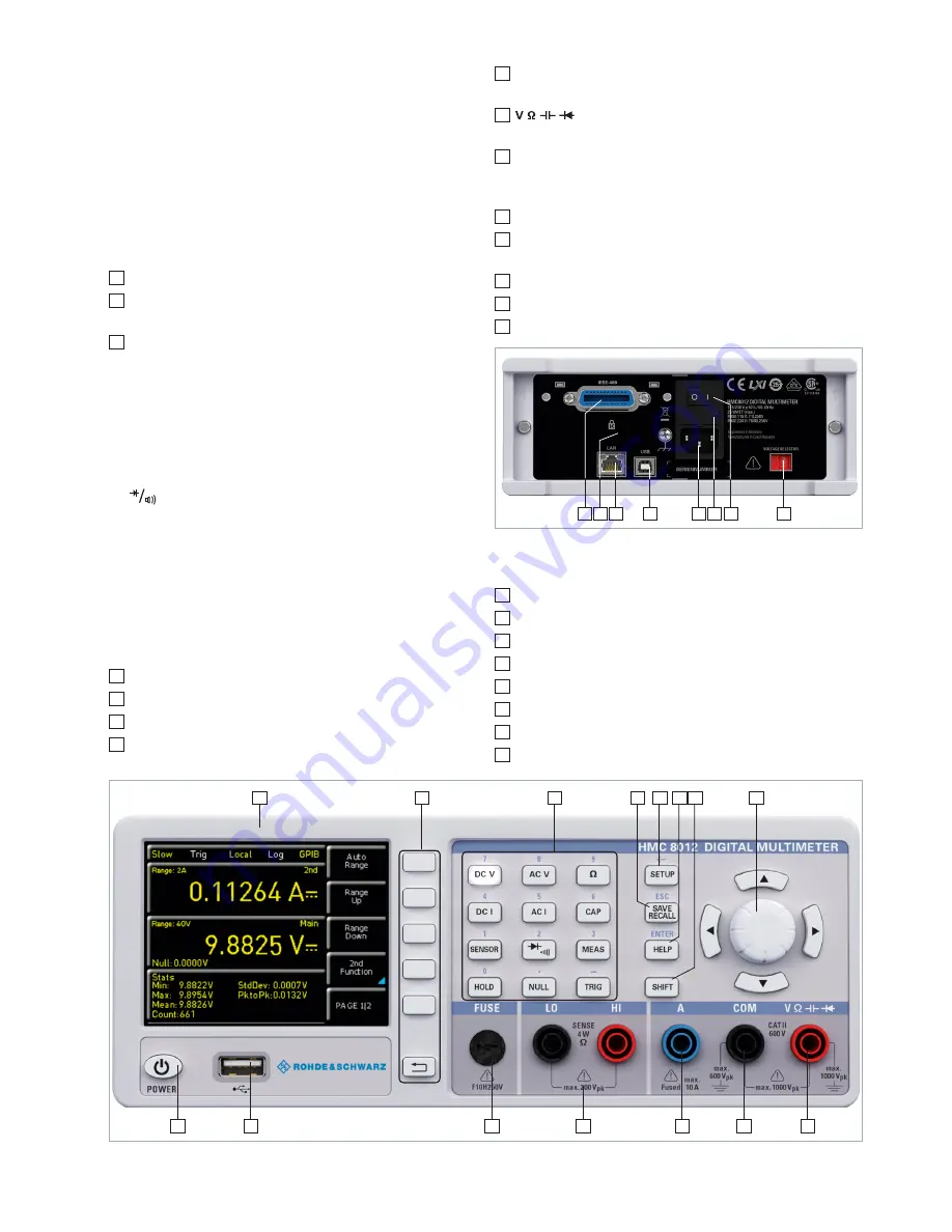
Front panel of the instrument
1
Display – Color display (320 x 240 pixel)
2
Interactive soft menu keys – All relevant functions are
directly accessible
3
Function keys – To be used as numeric keypad in SHIFT
function
DC V – DC voltage measurement
DC I – DC current measurement
AC V – AC voltage measurement
AC I – AC current measurement
Ω – Resistance measurement, 2- and 4-wire
- diode / transmission measurement
SENSOR – Temperature measurement
HOLD – Measurement with hold function
NULL – Zero point of the measurement section
CAP – Capacity measurement
MEAS – Limit measurement / mathematical functions /
statistic
TRIG – Manual trigger
4
SAVE/RECALL – Loading/storing of instrument settings
5
SETUP – Access to basic instrument settings
6
HELP – Integrated help display
7
SHIFT – Shift key to activate the numeric keypad
8
Universal knob with arrow keys – Setting desired va-
lues (edit keys)
9
connector – Input for voltage, frequency, re-
sistance and temperature measurement
10
COM connector – Common measurement input
for voltage, resistance, temperature and capacity
measurement
11
A connector – Input for current measurement
12
LO/HI connectors – Sensor for resistance and tempera-
ture measurement
13
FUSE – Measuring circuit fuse
14
USB connector – USB connector to save parameters
15
POWER – On/Off for standby mode
Rear panel of the instrument
16
IEEE-488 (GPIB) interface (option) – Factory-installed only
17
Kensington lock
18
LAN connector
19
USB connector
20
Low-heat device socket with power switch
21
Fuse
22
Power switch
23
Voltage selector (115 V or 230 V)
Fig. 2.1: Front panel of the ¸HMC8012
1
2
3
4
5
8
6 7
9
10
11
12
13
14
15
Fig. 2.2: Rear panel of the ¸HMC8012
23
20 21 22
19
18
17
16
Содержание HMC8012
Страница 34: ...34 Anhang ...
Страница 66: ...66 Appendix ...
Страница 67: ...67 Appendix ...
Страница 68: ...68 Appendix ...


