Rohde & Schwarz 1145.5850.03 Скачать руководство пользователя страница 46

Selecting the Instrument Default Setup 

R&S FSH  

1145.5973.12 1.12 

E-11 

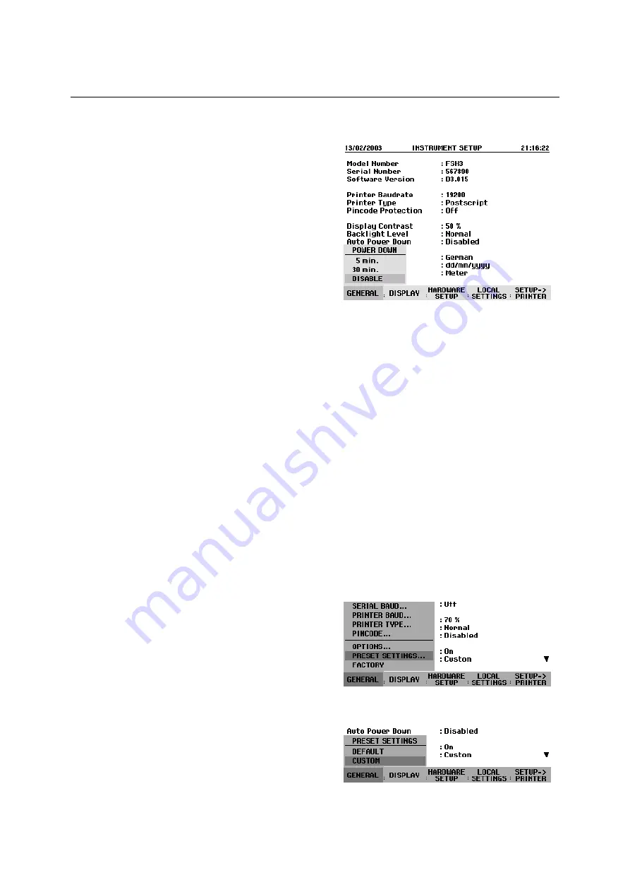
The auto power down mode is set as follows: 
 

!

 Press the GENERAL key. 

The R&S FSH opens the submenu with the general 
settings. The cursor is positioned to POWER DOWN in 
the menu. 
 

!

 Confirm the POWER DOWN selection by pressing 

the ENTER key. 

The R&S FSH opens a selection window with the settings: 

5 minutes, 30 minutes and DISABLE. 

!

 Using the rotary knob or cursor keys, select the 

setting you want and confirm by pressing the 
ENTER key or the GENERAL softkey. 


Selecting the Instrument Default Setup 

The PRESET key sets the R&S FSH to the default setup. This allows a new configuration based on 
defined measurement parameters to be entered, without parameters from a previous setting 
unintentionally still being active. 

!

 Press the PRESET key. 

The R&S FSH is set to the default setup. The span depends on the model. With the R&S FSH3, it is 
3 GHz; with the R&S FSH6, 6 GHz. 

If certain parameters are always to deviate from the default setup for a specific application, it is also 
possible to select a user-defined default setup, which is then automatically set with the PRESET key. 
This is useful, for example, if the measurement is always made with a 75 

 matching pad. When the 

PRESET key is pressed, the R&S FSH always selects 75 

 as the input impedance for the user-

specific default setup. The user-defined default setup is generated by manually entering the desired 
parameters and saving the setting as a data set. This data set can subsequently be declared the preset 
settings with the aid of the R&S FSH View software. 

The data set designated as the preset settings becomes the default setup of the R&S FSH as follows: 
 

!

 Press the SETUP key. 

!

 Press the GENERAL softkey. 

!

 Select PRESET SETTINGS from the menu using 

the cursor keys or the rotary knob. 

!

 Confirm your choice with the ENTER key or the 

GENERAL softkey. 

The submenu for selecting the default setup opens. Either DEFAULT or CUSTOM can be selected. 
 

!

 Select CUSTOM from the menu using the cursor 

keys or the rotary knob. 

!

 Confirm your choice with the ENTER key or the 

GENERAL softkey. 

Содержание 1145.5850.03

Страница 1: ...1145 5973 12 11 1 Test and Measurement Division Operating Manual Handheld Spectrum Analyzer R S FSH 1145 5850 03 1145 5850 13 1145 5850 23 1145 5850 06 1145 5850 26...

Страница 2: ...1145 5973 12 11 2 Dear Customer R S is a registered trademark of Rohde Schwarz GmbH Co KG Trade names are trademarks of the owners...

Страница 3: ...ching on the Spectrum Analyzer 1 4 Spectrum Analyzer Connectors 1 5 Screen Settings 1 7 Country Specific Settings 1 9 Setting the Date and Time 1 10 Setting the date 1 10 Setting the time 1 10 Chargin...

Страница 4: ...ments with the R S FSH Z14 or the R S FSH Z44 2 7 Two Port Transmission Measurements 2 9 Measurement of Return Loss 2 11 Performing Distance To Fault Measurements 2 14 Operation in Receiver Mode 2 20...

Страница 5: ...elected 3 2 Entering Measurement Parameters 3 3 Entering values and texts 3 3 Entering units 3 4 Menu Overview 3 5 Frequency entry 3 5 Frequency span 3 5 Level setting 3 5 Bandwidth setting 3 5 Sweep...

Страница 6: ...evel 4 8 Entering the display range 4 8 Entering the display unit 4 9 Entering the reference offset 4 9 Entering the input impedance 4 10 Setting the Bandwidths 4 11 Resolution bandwidth 4 11 Video ba...

Страница 7: ...l bandwidth 4 48 Displaying the occupied bandwidth 4 48 Changing the span 4 49 Measuring the Carrier to Noise Ratio 4 50 Determining the reference 4 51 DIGITAL Tx mode 4 51 ANALOG TV mode 4 52 CW Tx m...

Страница 8: ...the unit for the power readout 4 79 Taking additional attenuation into account 4 80 Two port measurements with the tracking generator 4 82 Measuring the transmission of two ports 4 84 Vector transmis...

Страница 9: ...asuring with Transducer Factors 4 122 Unit for measurements with transducers 4 124 Reference level settings for measurements with transducers 4 124 Frequency range of transducer 4 125 Data sets contai...

Страница 10: ...dBc 1 Hz 100 kHz from carrier 100 dBc 1 Hz 1 MHz from carrier 120 dBc 1 Hz Sweep time span 0 Hz 1 ms to 100 s span 0 Hz 20 ms to 1000 s min 20 ms 600 MHz Bandwidths Resolution bandwidths 3 dB 1145 585...

Страница 11: ...Bm 80 dBm Input related spurious Up to 3 GHz 3 GHz to 6 GHz Signal frequency minus 2 0156 GHz for signal frequencies 2 GHz to 3 2 GHz mixer level 40 dBm carrier offset 1 MHz 70 dBc nominal typ 55 dBc...

Страница 12: ...typ 1 5 typ 1 5 Trigger external reference input BNC female selectable Trigger voltage TTL Reference frequency 10 MHz Required level from 50 10 dBm Outputs AF output 3 5 mm mini jack Output impedance...

Страница 13: ...8 GHz 8 GHz to 18 GHz 15 C to 35 C 0 C to 50 C 15 C to 35 C 0 C to 50 C 2 3 0 10 dB 4 2 0 18 dB 3 5 0 15 dB 5 0 0 21 dB Zero offset after zeroing 110 pW Dimensions 48 mm x 31 mm x 170 mm connecting c...

Страница 14: ...certainty 18 C to 28 C same as for average power plus effect of peak hold circuit Error limits of peak hold circuit for burst signals Duty cycle 0 1 and repetition rate 100 s 20 s repetition rate 100...

Страница 15: ...Data Sheet R S FSH3 and R S FSH6 1145 5973 12 TI 6 E 11 Power handling capacity Dimensions 120 mm x 95 mm x 39 mm connecting cable 1 5 m Weight 0 65 kg...

Страница 16: ...tainty 200 MHz to 300 MHz 300 MHz to 4 GHz sine signal 18 C to 28 C no zero offset 4 0 of measured value 0 17 dB 3 2 of measured value 0 14 dB Zero offset after zeroing 4 mW Range of typical measure m...

Страница 17: ...s plus 1 6 of measured value 0 15 W plus 0 10 W plus 5 of measured value plus 10 of measured value Range of typical measure ment error of peak hold circuit for cdmaOne DAB DVB T CDMA2000 3GPP WCDMA vi...

Страница 18: ...wer handling capacity PEAK max 10 ms SWR 3 AVG 10 C to 35 C SWR 1 5 Forward power Frequency 0 2 0 4 0 7 1 2 3 4 GHz 100 200 400 600 800 1000 AVG 10 C to 35 C SWR 3 AVG 35 C to 50 C SWR 3 Dimensions 12...

Страница 19: ...to 50 MHz 50 MHz to 3 GHz 3 GHz to 6 GHz typ 20 dB typ 20 dB 12 dB typ 18 dB 16 dB typ 22 dB 16 dB typ 22 dB Return loss at test port corrected 2 MHz to 3 GHz 3 GHz to 6 GHz option R S FSH K2 typ 35...

Страница 20: ...and R S FSH6 model 1145 5850 26 Display 301 pixels Maximum resolution distance to fault maximum zoom cable length 1023 pixels Display range Return loss VSWR 10 5 2 1 dB div linear 1 to 2 and 1 to 6 w...

Страница 21: ...typ 65 dB typ 80 dB typ 90 dB typ 70 dB typ 85 dB typ 40 dB typ 55 dB typ 35 dB typ 50 dB Reflection measurements only with R S FSH3 model 1145 5850 13 or 1145 5850 23 R S FSH6 model 1145 5850 26 and...

Страница 22: ...utes per axis Shock complies with EN 60068 2 27 40 g shock spectrum RFI suppression complies with EMC directive of EU 89 336 EEC and German EMC legislation Immunity to radiated interference Level disp...

Страница 23: ...C for the R S FSH R S FSH K1 1157 3458 02 Vector Transmission and Reflection Measurements for the R S FSH R S FSH K2 1157 3387 02 Receiver Mode for the R S FSH R S FSH K3 1157 3429 02 Optional access...

Страница 24: ...Spare 50 Load Standard for R S FSH Z2 for VSWR and DTF calibration DC to 3 GHz R S FSH Z31 1145 5780 02 Spare Battery Pack for the R S FSH R S FSH Z32 1145 5796 02 Spare AC Power Supply for the R S FS...

Страница 25: ...be changed accordingly 5 If the unit has no power switch for disconnection from the AC supply the plug of the connecting cable is regarded as the disconnecting device In such cases it must be ensured...

Страница 26: ...suitably cleaned using a soft lint free dustcloth Never use solvents such as thinners acetone and similar things as they may damage the front panel labeling or plastic parts 12 Any additional safety i...

Страница 27: ...sured of receiving a product that is manufactured using the most modern methods available This product was developed manufactured and tested in compliance with our quality management system standards...

Страница 28: ...the approximation of the laws of the Member States relating to electrical equipment for use within defined voltage limits 73 23 EEC revised by 93 68 EEC relating to electromagnetic compatibility 89 3...

Страница 29: ...onday through Friday from 8 00 until 17 00 If you need assistance outside office hours please leave a message or send us a fax or e mail We will contact you as soon as possible If you wish to receive...

Страница 30: ...Buenos Aires Tel 541 14 331 10 67 Fax 541 14 334 51 11 alberto lombardi prec elec com ar Argentina Rohde Schwarz Australia Pty Ltd Sales Support Unit 6 2 8 South Street Rydalmere N S W 2116 Tel 61 2 8...

Страница 31: ...Berlin Tel 49 30 34 79 48 0 Fax 49 30 34 79 48 48 info rsv rohde schwarz com Zweigniederlassung B ro Bonn Josef Wirmer Stra e 1 3 D 53123 Bonn Postfach 140264 D 53057 Bonn Tel 49 228 918 90 0 Fax 49 2...

Страница 32: ...com jo Jordan Rohde Schwarz Kazakhstan Representative Office Almaty Pl Respubliki 15 480013 Almaty Tel 7 32 72 67 23 54 Fax 7 32 72 67 23 46 rs kazakhstan rsd rohde schwarz com Kazakhstan Excel Enter...

Страница 33: ...rabia Gentec Haji Abdullah Alireza Co Ltd P O Box 43054 Riyadh Tel 966 1 293 20 35 Fax 966 1 466 16 57 akanbar gentec com sa Saudi Arabia Rohde Schwarz Representative Office Belgrade Tose Jovanovica 7...

Страница 34: ...Mobile Communication P O Box 17466 JAFZ PPU ZG 07 Dubai Tel 971 4 883 71 35 Fax 971 4 883 71 36 Rohde Schwarz Emirates L L C ESNAAD Premisses at Mussafah P O Box 31156 Abu Dhabi Tel 971 2 55 49 411 Fa...

Страница 35: ...play RS 232 C optical interface Connector for AC power supply Softkeys Function keys Entry keys Cursor keys Unit keys Generator output N connector RF input N connector Connector for headphones Softkey...

Страница 36: ...upper and lower shells The two shells are held together by tape The packaging contains all accessories supplied Undo the tape to unpack the analyzer Upper shell Lower shell CD ROM Headphones Quick St...

Страница 37: ...e the optimum viewing angle for the display For use as a desktop fold out the support at the rear so that the instrument can easily be operated from the front and the display can be read easily see Fi...

Страница 38: ...he power supply unit Before inserting the power supply unit into the AC power outlet attach the appropriate adapter In vehicles the battery can be charged from the cigarette lighter socket using the R...

Страница 39: ...is applied to start a measurement or a 10 MHz reference signal is applied for frequency synchronization The trigger threshold is similar to that of TTL signals The level for the reference signal must...

Страница 40: ...for printers with a parallel interface Printers with a USB interface cannot be connected directly to the R S FSH Connector for power sensor The connector has been especially configured for Rohde Schw...

Страница 41: ...and confirm by pressing the DISPLAY softkey or the ENTER key again The BACKLIGHT submenu for the lighting level opens The level can be set to HIGH NORMAL and LOW Using the rotary knob or cursor keys...

Страница 42: ...the contrast lighting and color settings opens Using the rotary knob or cursor keys select TYPE and confirm with the ENTER key or by pressing the DISPLAY softkey again In the submenu that opens select...

Страница 43: ...displayed in a submenu The selected language is highlighted in red Using the rotary knob or cursor keys select the language you want The originally selected language is highlighted in green The red ba...

Страница 44: ...to the second field in the date day or month depending on the date format Proceed with the next two fields as with the first After the last data block has been entered the R S FSH verifies the validit...

Страница 45: ...five steps until just the battery outline indicates that the battery is flat Battery charge level symbol The battery is charged via the included power supply unit which is connected to the jack on th...

Страница 46: ...meters are always to deviate from the default setup for a specific application it is also possible to select a user defined default setup which is then automatically set with the PRESET key This is us...

Страница 47: ...set not overwritable or deletable Data set overwritable Status field External Reference External Trigger Switchover The Ext Trig Ext Ref BNC connector on top of the R S FSH can be used either as an i...

Страница 48: ...knob or cursor keys select LOW NOISE or LOW DISTORTION Confirm with the ENTER key or the HARDWARE SETUP softkey Using a Preamplifier Only models 1145 5850 03 1145 5850 23 1145 5850 06 and 1145 5850 26...

Страница 49: ...el Preamplifier OFF Preamplifier ON Reference level RF attenuation RF attenuation Preamplifier Low Noise Low Distortion Low Noise Low Distortion 25 dBm 0 dB 0 dB 0 dB 0 dB On 24 dBm to 20 dBm 0 dB 0 d...

Страница 50: ...0 After you enter your valid PIN the PIN functions can be selected from the selection box When the R S FSH is delivered a new PIN can be activated only if it differs from the factory set PIN Note Befo...

Страница 51: ...SH comes with labels reading PIN Code protected If the instrument is protected with a PIN affix one of these labels to the instrument This warns unauthorized users that they cannot operate the R S FSH...

Страница 52: ...a parallel interface to the R S FSH using the Serial Parallel Converter R S FSH Z22 thus freeing up the Centronics parallel interface to connect a printer The R S FSH Z22 is powered by a 9 V alkaline...

Страница 53: ...sor keys select the printer you want and confirm with the ENTER key or by pressing the GENERAL softkey again The R S FSH displays the selected printer under Printer Type Next set the baud rate for the...

Страница 54: ...ENERAL softkey again The R S FSH displays the selected baud rate under SERIAL BAUDRATE in the setup display Enabling Options The R S FSH can be fitted with options e g distance to fault measurements o...

Страница 55: ...Installed Options The R S FSH displays the installed options in the Setup menu so you can check them Press the SETUP key Using the rotary knob or the cursor keys scroll the status display downwards Th...

Страница 56: ...is used as a signal source e g the Signal Generator R S SML Measurement setup Connect the RF output of the signal generator to the RF input of the R S FSH Signal generator settings Frequency 100 MHz...

Страница 57: ...by spectrum analyzers at the top of the measurement diagram is called the reference level REF LEVEL To obtain the best dynamic range from a spectrum analyzer its full level range should be used This m...

Страница 58: ...requency from the measurement point frequency and the center frequency and frequency span that have been set The measurement point resolution and consequently the accuracy of the marker frequency read...

Страница 59: ...ayed as lines at frequencies that are multiples of 100 MHz To measure the second harmonic ratio set the start and stop frequency as follows Press the FREQ key The softkey menu opens entering the frequ...

Страница 60: ...he maximum permissible power for the sensor is never exceeded when measurements are made on high power transmitters Connect the power sensor cable to the R S FSH s power sensor connector and screw it...

Страница 61: ...outputs the message Zeroing power sensor please wait When zeroing is over the R S FSH outputs the message Power Sensor Zero OK and switches back to the softkey menu for the power sensor Connect the s...

Страница 62: ...terface The cable on the power sensor must be connected and screw fastened to the power sensor connector on the R S FSH The directional power sensor itself has to be inserted between the source and th...

Страница 63: ...or 5 CANCEL can be used to cancel zeroing before it begins e g if the signal source cannot be disconnected The R S FSH immediately starts power sensor zeroing While this is being done the R S FSH out...

Страница 64: ...d on the R S FSH displays Track Gen Uncal This indicates that tracking generator measurements are uncalibrated Before calibration the span you want should be set because calibration is valid only for...

Страница 65: ...FSH displays the magnitude of the transfer function You can read out values with the markers for example The transmission calibration remains valid until the center frequency or the span is changed on...

Страница 66: ...s are made This is done with a short and an open at the point were the reflection measurement is to be made If a cable is to be inserted between the DUT and the bridge perform the calibration at the m...

Страница 67: ...Using the CONTINUE softkey start the OPEN cali bration While calibration is in progress the R S FSH outputs the message Calibrating OPEN please wait When OPEN calibration is over the R S FSH prompts...

Страница 68: ...the Reflection display to indicates possible increase in measurement uncertainty When saving a data set for a scalar reflection measurement in a calibrated state the R S FSH can store the calibration...

Страница 69: ...RF and generator port of the R S FSH Z2 R S FSH Z3 to the RF input and generator output of the R S FSH Connect the 1 m test cable supplied with option R S FSH B1 to the bridge test port Note The 1 m c...

Страница 70: ...ays the cable used for the measurement in the upper right hand corner of the screen Entering the cable parameters at a specific frequency If cables are used that are not listed in cable models stored...

Страница 71: ...meric keys enter the cable length in meters and terminate the entry with the ENTER key or one of the unit keys or Using the rotary knob 1 m steps or the cursor keys 10 m steps adjust the cable length...

Страница 72: ...R S FSH displays the return loss produced in the cable under test versus the distance The R S FSH can also list any cable faults It displays the return loss and distance from the measurement plane of...

Страница 73: ...ON from the menu Confirm with the ENTER key The entry field for the zoom factor is displayed while the R S FSH simultaneously expands the x axis by a factor of 2 Using the rotary knob or the cursor k...

Страница 74: ...in the span for detecting external interferers Press the MEAS MODE softkey Using the rotary knob or cursor keys select SPECTRUM Confirm by pressing the MEAS MODE softkey again or by pressing the ENTE...

Страница 75: ...s opens Using the rotary knob or the cursor keys select RECEIVER from the menu and confirm with the ENTER key or the MEASURE softkey The R S FSH activates the receiver mode and measures the level at t...

Страница 76: ...R S FSH can also be tuned in channels The channel tables that the R S FSH uses to set channel frequencies are defined either by using the R S FSH View software or by directly entering the first chann...

Страница 77: ...cursor keys select NO OF CHANNELS from the menu and confirm with the ENTER key Enter the number of channels and confirm with the ENTER key Press the DEFINE USER TAB softkey Using the rotary knob or th...

Страница 78: ...e suitable bandwidth dependent on the set frequency Setting the detector The receiver mode of the R S FSH offers a peak detector average detector RMS detector and quasi peak detector Set the detector...

Страница 79: ...ches to the scan mode and displays the measurement levels at the individual frequencies as vertical lines Press the SCAN START softkey Enter the start frequency for the scan Press the SCAN STOP softke...

Страница 80: ...of the vision carrier is measured This is common with amplitude modulated TV signals CW Tx In the CW Tx operating mode the power of an unmodulated carrier is measured Manual entry of a reference power...

Страница 81: ...Entering the channel bandwidth of the reference channel If the reference measurement is active press the CHANNEL BW softkey Enter the desired value and terminate the entry with the appropriate unit k...

Страница 82: ...r measurement is active press the CHANNEL BW softkey Enter the desired value and terminate the entry with the appropriate unit key The R S FSH sets the span in accordance with the selected bandwidth T...

Страница 83: ...you can instruct the R S FSH to browse through the list of names of the data sets already stored and display them with the first available free extension Thus the name of the data set recalled for a s...

Страница 84: ...h memory space as without it This of course reduces the maximum number of data sets that can be saved In the default state calibration data storage is disabled Press the SETUP key Press the GENERAL so...

Страница 85: ...ings and results for each data set are displayed You now have the following options Press the STATUS key to see all the instrument settings in the selected data set When you press the STATUS key again...

Страница 86: ...l converter R S FSH Z22 is available Printer with serial interface Connect the printer to the optical interface using the RS 232 C optical interface cable R S FSH Z34 Printer with parallel interface C...

Страница 87: ...markers Trace Softkey labelling Battery charge level indicator X axis scale Level axis scale Reference level display Detector display Value entry box Status message Invalid trace symbol Grid Display...

Страница 88: ...led The colour of the softkey labelling and its background indicate the status of the softkey function in question Softkey colour Meaning Blue background white labelling Softkey function is turned off...

Страница 89: ...letter entry it automatically assigns the letters above the keys to the keys in the alphanumeric keypad The keys have multiple assignments The letter you want is obtained by pressing the key the appro...

Страница 90: ...rminate the entry with a unit key Use the unit keys down the right hand side of the alphanumeric keypad These keys have multiple assignments which depend on the unit entry expected by the R S FSH GHz...

Страница 91: ...PAN LAST SPAN Level setting AMPT REF RANGE UNIT REF OFFSET RF INPUT 10 dB DIV 5 dB DIV 2 dB DIV 1 dB DIV 0 1 dB DIV LIN 0 100 VSWR 1 REFL COEFF ROH 1 REFL COEFF mROH 1 SMITH CHART 1 2 dBm dBmV dBHV V...

Страница 92: ...E SWEEP TRIGGER FREE RUN VIDEO EXTERN EXTERN DELAY Trace setting TRACE TRACE MODE TRACE MEMORY SHOW MEMORY DETECTOR AUTO COUPLED AUTO PEAK MIN PEAK MAX PEAK SAMPLE RMS CLEAR WRITE AVERAGE MIN HOLD MAX...

Страница 93: ...CT SELECT USER MOD EXIT DEFINE USER MOD LIST PRINTER THRES HOLD LIST PRINTER EXIT MANUAL SWPTIME Option FSH K2 only STANDARD LEVEL ADJUST PWR UNIT CHANNEL BW POWER DISPLAY USER 3GPP WCDMA CDMAONE CDMA...

Страница 94: ...Menu Overview R S FSH 1145 5973 12 3 8 E 11 Power meter menus Transducer menus MEASURE MEAS TRANS DUCER LIMIT LINES DISPLAY LINE TRANSD TRANSD dB EXIT TRD S OFF SELECT TRANSD OFF EXIT LIST PRINTER...

Страница 95: ...nus UPPER LIMIT LOWER LIMIT EXIT LIMITS OFF OPTIONS SELECT LIMIT OFF EXIT LIST PRINTER MEASURE MEAS TRANS DUCER LIMIT LINES DISPLAY LINE BEEP MESSAGE VSWR LIMIT EXIT OPTIONS BEEP MESSAGE Smith Chart O...

Страница 96: ...MARKERS ON ALL MARKERS OFF DELTA 2 DELTA 3 DELTA 4 DELTA 5 DELTA 6 ALL DELTAS ON ALL DELTAS OFF Distance to fault mode option R S FSH B1 DISTANCE MARKER MARKER MARKER OFFSET SET MARKER MARKER MODE MK...

Страница 97: ...E JAPANESE CHINESE KOREAN PRINTER BAUDRATE 1200 Baud 2400 Baud 9600 Baud 19200 Baud 38400 Baud 57600 Baud 115200 Baud PRINTER DESKJET LASERJET EPSON FX POSTSCRIPT PINCODE PINCODE OFF PINCODE ON NEW PI...

Страница 98: ...ES DISPLAY LINE ANALYZER RECEIVER TRACKING GEN POWER SENSOR CHANNEL POWER OCCUPIED BW TDMA POWER DISTANCE TO FAULT FREQ REF LEVEL BAND WIDTH MEAS TIME DETECTOR FREQ key Frequency entry FREQ FREQ FREQ...

Страница 99: ...START SCAN STOP SCAN STEP Channel entry SPAN FIXED CHANNEL CHANNEL SCAN FREQ START FREQ STOP Channel scan SPAN FIXED CHANNEL CHANNEL SCAN FREQ START FREQ STOP AMPT key AMPT REF RANGE UNIT REF OFFSET...

Страница 100: ...ER FREE RUN VIDEO EXTERN EXTERN DELAY Trace key Measurement at a fixed frequency TRACE TRACE MODE TRACE MEMORY SHOW MEMORY DETECTOR TRACE STYLE PEAK AVERAGE RMS QUASI PEAK Scan mode TRACE TRACE MODE T...

Страница 101: ...display can be output directly to a printer as measurement documentation At a later date every detail of a measurement can therefore be accurately reproduced Operating sequence Press the STATUS key ab...

Страница 102: ...ve you can change the center frequency with the rotary knob or the cursor keys and terminate the entry with the ENTER key You can clear the value entry box from the screen by pressing the CANCEL key T...

Страница 103: ...setting the step size is equal to 10 of the span 1 division on the vertical scale With CENTER the step size is equal to center frequency This setting is ideal for measurements on harmonics On each fr...

Страница 104: ...R S FSH3 which is greater than 3 GHz or you reach the 3 GHz limit with the rotary knob or the cursor keys the R S FSH3 outputs the message Maximum reached The limit on the R S FSH6 is 6 GHz Working wi...

Страница 105: ...the definition of the channel table used either Minimum reached is displayed on the screen when the lowest channel number is reached or Maximum reached is displayed when the highest channel number is...

Страница 106: ...MHz kHz or Hz or Change the span with the rotary knob or the cursor keys The span is set immediately after the change is made The value entry box can be cleared from the screen with the CANCEL key Us...

Страница 107: ...he RF attenuation but also the preamplifier if switched on is coupled to the reference level setting Preamplifier OFF Preamplifier ON Reference level RF attenuation RF attenuation Preamplifier Low Noi...

Страница 108: ...hlighted in red Enter a reference level with the number keys and either terminate the entry with one of the unit keys dBm or dBm for relative measurements or m O n for absolute measurements or press t...

Страница 109: ...ing the rotary knob or the cursor keys select the unit you want and confirm your selection by pressing the ENTER key The reference level unit is immediately set on the R S FSH Entering the reference o...

Страница 110: ...softkey A submenu opens The two input impedance options 50 and 75 are displayed Select the input impedance you want using the rotary knob or the cursor keys and confirm your selection by pressing the...

Страница 111: ...has an effect on the noise displayed by the spectrum analyzer If the bandwidth is small the noise displayed drops If the bandwidth is reduced or increased by a factor of 3 the noise displayed drops o...

Страница 112: ...Enter the resolution bandwidth you want using the number keys and terminate the entry with the appropriate unit MHz kHz or Hz or Change the resolution bandwidth to the value you want using the rotary...

Страница 113: ...ed the high frequency noise components above the cutoff frequency of the video filter will be rejected The smaller the video bandwidth the smaller the noise amplitude at the video filter output Theref...

Страница 114: ...he resolution bandwidth RBW a small red circle is placed before the video bandwidth readout in the top right hand corner of the screen Enter the video bandwidth you want with the number keys and termi...

Страница 115: ...red circle on the right hand side of the measurement diagram The R S FSH requires a minimum sweep time of 20 ms per 600 MHz of span If a larger span is set the R S FSH automatically adapts the minimu...

Страница 116: ...the CONT SWEEP softkey The R S FSH now sweeps continuously again Trigger To respond to events the R S FSH has a variety of trigger functions The trigger can either be external or generated internally...

Страница 117: ...e of the reference level 100 means that the trigger level equals the reference level 50 that the trigger level is in the middle of the y axis on the measurement diagram default setting The position of...

Страница 118: ...E 11 The trigger delay resolution depends on the delay selected The table below lists the values Trigger delay DELAY Resolution 0 to 1 ms 10 Os 1 ms to 10 ms 100 Os 10 ms to 100 ms 1 ms 100 ms to 1 s...

Страница 119: ...ith the trace pixels from the previous setting for example if the span is changed Intermittent signals in the spectrum or the maximum of fluctuating signals are easy to find with MAX HOLD MIN HOLD The...

Страница 120: ...ector is pixel oriented i e it determines how the level at each pixel will be displayed The R S FSH always measures the whole spectrum However the trace only has 301 pixels in the x direction for disp...

Страница 121: ...the greater the sweep time If you are making noise measurements for example the trace will be highly stable if a long sweep time is selected However the bandwidth occupied by the signal to be measured...

Страница 122: ...the ENTER key or the DETECTOR softkey The R S FSH indicates the detector that has been selected in the top left hand corner of the screen Detect Auto Pk in Fig above If AUTO COUPLED is switched on and...

Страница 123: ...y Therefore when the memory trace is recalled it will not be adapted to any modifications of the reference level or span that may have been made in the meantime When a stored data set is called the R...

Страница 124: ...the main marker in other words the delta marker frequency is the frequency difference between the frequency at the point marked by the main marker and the frequency at the point marked by the delta m...

Страница 125: ...er position PEAK This function places the marker or the delta marker on the highest value of the trace The function acts on the active marker whose associated softkey labelling is highlighted in red N...

Страница 126: ...onfirm your choice with the SET MARKER softkey or the ENTER key The R S FSH opens a submenu for setting the start and stop frequencies for the marker search range For entering the start of the search...

Страница 127: ...nals in a trace the R S FSH has the multimarker function Up to six different markers are available in the multimarker mode Marker 1 measures in absolute units Markers 2 to 6 can measure in absolute un...

Страница 128: ...the marker or delta marker near the position you want The step width here is 10 of the X axis Then use the rotary knob to fine tune the marker or delta marker to the signal The step width corresponds...

Страница 129: ...a markers If you press the MKR LIST VIEW softkey again or any other softkey in the marker menu the R S FSH closes the marker table Deactivating markers In multimarker mode markers can be deactivated o...

Страница 130: ...ternatively you can exit the multimarker mode by deactivating all markers MARKER key MARKER softkey ALL MARKERS OFF menu item or with PRESET Marker functions Apart from displaying the level and freque...

Страница 131: ...301 frequency coordinates The frequency resolution is therefore relatively coarse especially if a large span is set To circumvent this problem the R S FSH s internal frequency counter can be used Whe...

Страница 132: ...ically turns on the marker and positions it on the trace maximum Using the cursor keys or the rotary knob select the demodulation mode AM or FM you want and confirm your selection with the ENTER key N...

Страница 133: ...s Terminate the entry with the ENTER key The softkey label DISPLAY LINE is printed on a green background and the entry box is cleared In contrast to the markers the position of the displayed line is p...

Страница 134: ...olution bandwidth that is small in comparison with the channel bandwidth The measured values on the trace are then integrated to give the total power The R S FSH takes into account the selected displa...

Страница 135: ...key or the STANDARD softkey The R S FSH sets the selected standard The optimal span resolution bandwidth video bandwidth sweep time and detector for the standard are selected automatically If USER is...

Страница 136: ...g used by the R S FSH in the USER setting is immediately clear The name entered as the USER standard also appears on the screen thus making it possible to document the setting along with the measureme...

Страница 137: ...l within the measurement diagram To prevent the R S FSH from being overdriven the signal can be measured at the largest resolution bandwidth possible using the peak detector If this setting is selecte...

Страница 138: ...is 833 Hz at a span of 1 kHz Changing the span The span set by the R S FSH yields extremely precise measurement results However signals in the environment of the measurement channel are no longer dete...

Страница 139: ...ursor keys or the rotary knob and confirm with the ENTER key The power display will switch from Max Power to Power Power display The R S FSH displays the power at the bottom of the measurement diagram...

Страница 140: ...different units for power output The basic unit is dBm Press the PWR UNIT softkey The R S FSH opens the submenu with the units dBm dBmV and dBOV Using the rotary knob or the cursor keys select the re...

Страница 141: ...le signal lies within the selected resolution bandwidth If the resolution bandwidth is too narrow the displayed power will be lower than the actual power Press the MEAS key Press the MEASURE softkey T...

Страница 142: ...dard also appears on the screen thus making it possible to document the setting along with the measurement Press the STANDARD softkey A table with the available standards opens Select Rename USER with...

Страница 143: ...n the greatest possible dynamic range for burst signals the lowest reference level possible must be set If this is not done the R S FSH will be overdriven by the measurement signal if its maximum leve...

Страница 144: ...the trigger the R S FSH will trigger on the rising edge of the burst Should this not be the case the trigger level must be adjusted so that the R S FSH is triggered by the burst edge Otherwise no mea...

Страница 145: ...entered the R S FSH automatically selects the measurement parameters so that an optimal result is attained Operation Press the MEAS key Press the MEASURE softkey The R S FSH will open the measurement...

Страница 146: ...nges to the setting so that it is again available when USER is called again The following should be noted when changes to the settings are made The span is always coupled to the channel bandwidth CHAN...

Страница 147: ...corner of the screen after the USER standard is selected Using the R S FSH View control software additional standards can be generated and permanently loaded into the R S FSH You can also delete the f...

Страница 148: ...entry with the appropriate unit or Change the channel bandwidth with the rotary knob or the cursor keys and terminate the entry with the ENTER key or the CHANNEL BW softkey The R S FSH automatically...

Страница 149: ...pied bandwidth is set MANUAL SPAN entry is active for immediate entry of another span Using the numeric keys enter a new span and terminate the entry with the appropriate unit or Change the span with...

Страница 150: ...d is common with amplitude modulated TV signals CW Tx In the CW Tx operating mode the power of an unmodulated carrier is measured Manual entry of a reference power or reference level The R S FSH also...

Страница 151: ...following The span is preset to 1 2 times the reference channel bandwidth The span is always coupled to the channel bandwidth When changes are made the R S FSH automatically sets the appropriate span...

Страница 152: ...menu for selecting the reference measurement opens Using the rotary knob or the cursor keys select ANALOG TV and confirm your choice with the ENTER key or the F1 softkey The R S FSH starts the ANALOG...

Страница 153: ...ng mode the count marker is automatically activated After each sweep the marker is set to the highest power in the reference channel Marker power and marker frequency are indicated at the top edge of...

Страница 154: ...e noise channel measurement has been activated the NOISE MEASURE softkey is highlighted in green If DIGITAL Tx is set the R S FSH measures the power in accordance with the selected channel bandwidth M...

Страница 155: ...in comparison with the signal bandwidth the R S FSH may be overdriven although the trace is within the measurement diagram To prevent the R S FSH from being overdriven the signal can be measured at t...

Страница 156: ...y or the F2 softkey The C N reference is displayed in the selected unit Measuring the noise channel power and calculating the carrier power noise power The noise channel power is measured in an unoccu...

Страница 157: ...hat are more stable Press the NOISE MEASURE softkey to start the measurement For calculation purposes the R S FSH uses the reference value that was last measured or manually set During the noise chann...

Страница 158: ...3 models 1145 5850 03 and 1145 5850 13 If you attempt to enter a smaller channel bandwidth the R S FSH will automatically set 8 33 kHz and output the message Limit exceeded With the R S FSH3 model 114...

Страница 159: ...red C N or C No value C N measurement result display If the noise channel measurement is active the R S FSH inserts the C N measurement result at the bottom of the measurement diagram Usually this doe...

Страница 160: ...mum span for the channel power measurement is set MANUAL SPAN is activated to allow immediate entry of another span Using the numeric keys enter a new span and terminate the entry with the appropriate...

Страница 161: ...s on specified discrete frequencies using the selected measurement time per frequency Activating the receiver mode Press the MEAS key Press the MEASURE softkey The measurement function menu will open...

Страница 162: ...y knob or the cursor keys or enter a new receiving frequency via the numeric keypad The frequency is displayed immediately after the entry Setting the frequency step size The step size for tuning the...

Страница 163: ...les available in the instrument that were loaded with the R S FSH View software are displayed If no channel table is loaded No bands available is displayed Select the desired channel table using the r...

Страница 164: ...ELS from the menu and confirm with the ENTER key Enter the number of channels and confirm the entry with the ENTER key Press the DEFINE USER TAB softkey Select CHANNEL SPACING from the menu and confir...

Страница 165: ...mediately activates entry of the resolution bandwidth the MANUAL RES BW softkey is highlighted in red Change the current bandwidth with the cursor keys or the rotary knob or enter a new bandwidth via...

Страница 166: ...bandwidth The quasi peak evaluation for the C D band 30 MHz to 1000 MHz is coupled to the 120 kHz bandwidth The detector is selected either in the main menu of the receiver mode or by using the TRACE...

Страница 167: ...of the scan via the numeric keypad or change the start frequency using the rotary knob or the cursor keys Press the STOP SCAN softkey Enter the stop frequency of the scan via the numeric keypad or ch...

Страница 168: ...lighted in red in the table of channel tables The screenshot above shows a measurement using a channel table with frequency gaps Different segments that are not interconnected are specified using the...

Страница 169: ...or connector and screw into position The DUT is connected to the N connector on the power sensor Power Sensor R S FSH Z1 or R S FSH Z18 RF Connector Power Sensor Connector The continuous power applied...

Страница 170: ...e R S FSH outputs the following error messages Message Cause Remedy Error in zeroing signal at sensor A signal was present at the power sensor when zeroing was performed Unscrew the power sensor from...

Страница 171: ...want to perform measurements on another known signal the power sensor can be told what the center frequency is via the frequency entry mode FREQ softkey Press the FREQ softkey The frequency value ent...

Страница 172: ...puts the message Power sensor zero OK and switches back to the softkey menu for the power sensor Selecting the unit for the power readout The R S FSH can display measured power in relative units dBm o...

Страница 173: ...a short measurement time to produce a stabile accurate result In this case the FAST operating mode is recommended to obtain a high repetition rate for the measurement When the NORMAL setting is select...

Страница 174: ...FSET softkey The value entry box for the reference offset opens Using the rotary knob the cursor keys or the number keys enter the offset you want and confirm the entry with the ENTER key The offset i...

Страница 175: ...orresponding to the direction of forward power The directional power sensors are controlled and powered via a special serial interface The sensor cable is to be connected and screwed to the POWER SENS...

Страница 176: ...atus field and after a few seconds displays the type of the sensor connected R S FSH Z44 as well as the measured power In the event of incorrect operation or sensor malfunction the R S FSH outputs the...

Страница 177: ...nter frequency to the power sensor If a signal at another frequency is to be measured the new center frequency can be transferred to the power sensor by entering the frequency FREQ softkey Press the F...

Страница 178: ...er sensor Setting the power measurement weighting For forward power display the R S FSH provides both average power and peak envelope power Use the POWER DISPLAY softkey in the Power Sensor menu to sw...

Страница 179: ...g the units for forward power and reflected power display opens Using the rotary knob or the cursor keys select the parameter for which a unit is to be entered Confirm the parameter with the ENTER key...

Страница 180: ...r a number of common transmission standards Press the STANDARD softkey A menu with the selectable standards opens Select the desired standard using the rotary knob or the cursor keys Confirm with the...

Страница 181: ...aximum input level of the R S FSH Z14 or R S FSH Z44 a directional coupler or an attenuator has to be connected ahead of the power sensor In such cases the coupling attenuation of the directional coup...

Страница 182: ...ion and reflection measurements the magnitudes are corrected Vector calibration methods and measurements option R S FSH K2 are possible for increasing the dynamic range and the measurement accuracy Th...

Страница 183: ...or the frequency range are selected with the appropriate keys as in the spectrum analyzer mode When the MEAS key is pressed the softkey menu for the tracking generator is displayed Before calibration...

Страница 184: ...put and the DUT s output to the RF input of the R S FSH The R S FSH measures the magnitude of the DUT s transmission The operating sequence is explained below using a transmission measurement on a SAW...

Страница 185: ...oftkey F1 or F2 CONTINUE to start calibration To abort calibration press the fourth or fifth softkey CANCEL During calibration the R S FSH outputs the message Calibrating THROUGH please wait Calibrati...

Страница 186: ...en such a data set is recalled measurements can be performed without prior calibration providing the instrument s temperature does not deviate more than 5 C from its temperature when the data set was...

Страница 187: ...The trace offset function is useful if it is necessary to compensate for a fixed loss or gain during the measurement Vector transmission measurement only with option R S FSH K2 With vector measuremen...

Страница 188: ...the tracking generator output without the DUT Press the F1 or F2 CONTINUE softkey to start calibration By pressing the F4 or F5 CANCEL softkey calibration can be aborted During calibration the R S FS...

Страница 189: ...To eliminate having to repeatedly mount and dismount the VSWR bridge the VSWR Bridge R S FSH Z3 10 MHz to 6 GHz includes a switch that bypasses the VSWR bridge and simultaneously switches the trackin...

Страница 190: ...of the VSWR bridge is incorporated into the measurement This corrective step requires that the control cable for automatically detecting the bridge be connected to the R S FSH Since the value is merel...

Страница 191: ...s setting may be useful if you only work with the R S FSH Z3 connected and do not want to waste time on automatic detection Supplying DC voltage to active DUTs By using the VSWR Bridge R S FSH Z3 DC v...

Страница 192: ...Connect an open to the measurement port of the bridge By pressing the first or the second softkey CONTINUE start the OPEN calibration While calibration is in progress the R S FSH outputs the message...

Страница 193: ...e measurement port of the VSWR bridge The R S FSH displays the return loss of the DUT Entering the display unit Press the AMPT key Press the RANGE softkey The submenu for selecting the display ranges...

Страница 194: ...weep time or measurement range has no effect on measurement accuracy This means they can be changed after calibration without any reduction in accuracy When a data set for scalar reflection measuremen...

Страница 195: ...or the MEAS MODE softkey Calibration Before the R S FSH is calibrated the desired center frequency and span must be set If they are set later the calibration values are lost and the calibration must b...

Страница 196: ...measurement uncertainty must be anticipated The R S FSH retains the calibration data but displays a red dot before the Refl vect display in the top right hand corner of the screen to indicate a possi...

Страница 197: ...the Smith chart Press the MARKER key The R S FSH activates the marker menu and a marker Using the rotary knob cursor keys or numeric entry move the marker on the complex impedance trace The numeric ou...

Страница 198: ...e displayed VSWR limit value to the desired value by using the rotary knob or enter a new limit value by using the numeric keys Press the ENTER key to complete the entry To deactivate the VSWR limit v...

Страница 199: ...e the size of the zoom window or the zoom factor Press the ZOOM FACTOR softkey Select the desired zoom factor 2 4 or 8 by using the rotary knob or cursor keys or by entering a numeric value Confirm th...

Страница 200: ...ement on an antenna for example it is useful to switch to the spectrum display To eliminate having to dismount the VSWR bridge each time a typical value for the insertion loss of the VSWR bridge is in...

Страница 201: ...by using the rotary knob or the cursor keys and confirm the entry with the HARDWARE SETUP softkey or the ENTER key If you select AUTO DETECT the VSWR bridge is detected automatically as soon as the co...

Страница 202: ...ftkey Set the required frequency range on the R S FSH Switch on vector measurement MEAS key MEAS MODE softkey VECTOR menu item Calibrate the R S FSH MEAS key RELECT CAL softkey Connect the cable to be...

Страница 203: ...eflected at a fault relative to the generator signal there is either reinforcement or cancellation Because of this effect there is ripple on the received sum signal in the frequency domain The R S FSH...

Страница 204: ...the cable Cable selection Frequency dependent cable models can be generated with the supplied R S FSH View Windows software package and loaded into the R S FSH The procedure is described in the R S FS...

Страница 205: ...at a user defined cable model has been selected The cable model can be checked or modified using the DEFINE USER MOD softkey Press the DEFINE USER MOD softkey A menu for entering the frequency the vel...

Страница 206: ...iberately entering a cable length that is too short is a good way of increasing distance to fault accuracy for a fault that is near to the measurement plane If the entered cable length is greater than...

Страница 207: ...e span and then the center frequency This prevents a message from being output stating that the desired center frequency cannot be set for the span currently being used for the distance to fault measu...

Страница 208: ...cted as an OPEN is not defined as precisely as a SHORT Note The reference plane must be the output of the 1 m measurement cable i e the measurement cable may not be dispensed with If the output of the...

Страница 209: ...valid however the instrument temperature must not change by more than 5 C after calibration If the temperature changes by more than 5 C a red circle is placed ahead of DTF CAL to indicate that there...

Страница 210: ...l other units a window for selecting the display range scaling opens You can select a display range by using the cursor keys or the rotary knob Confirm the selection by pressing the ENTER key or the R...

Страница 211: ...ey Locating cable faults by means of the marker function The distance to cable faults or the distance between any two faults can also be read off with the marker Press the MARKER key The R S FSH opens...

Страница 212: ...s step 10 of the span As is the case with spectrum analysis the R S FSH provides functions to automatically position the marker or the marker offset on the trace These can all be accessed by pressing...

Страница 213: ...m the preceding measurement zoomed by the factor 6 Faults mainly at the end of the cable can thus be clearly distinguished Switch the zoom function off as follows Press the MARKER MODE softkey in the...

Страница 214: ...n be defined for the distance to fault measurement If a marker offset is defined all distance values output by the R S FSH are referenced to the position of the offset marker Automatic marker position...

Страница 215: ...indicate that the R S FSH is measuring return loss DTF refl cal is displayed in the top right hand corner of the screen Further information Setting the span If automatic setting AUTO SPAN is used the...

Страница 216: ...re N number of measurement points SPAN manually set span AUTOSPAN span used by the R S FSH in automatic setting of the span In the above measurement example the resolution is thus 202 points for a cab...

Страница 217: ...orrection values from calibration It then calculates the IFFT result into length units from the cable parameters light velocity and frequency range In addition the R S FSH considers the attenuation of...

Страница 218: ...mask on the screen remains unchanged The points on the y axis are always dB values If the scale on the y axis is linear unit V or W the R S FSH automatically switches to the respective dB unit after a...

Страница 219: ...dist Distance DTF distance to fault measurements It is also indicated whether the limit lines are assigned to absolute frequency time or distance values abs or whether they are specified relative the...

Страница 220: ...alues are within specified limits PASS is displayed at the top in the center of the diagram FAIL is indicated even if only a single measured value pixel of the trace exceeds a limit value As long as a...

Страница 221: ...splayed span a check is not performed outside the definition range Data sets containing limit lines The R S FSH stores data sets together with any limit lines that may have been active for the measure...

Страница 222: ...s in this chapter Interpolation between the values is performed with the aid of a modified spline algorithm Even if only relatively few values such as maxima minima and turning points are available th...

Страница 223: ...With EXIT the transducer menu can be quit with TRD S OFF all transducer factors can be switched off Press the TRANSD softkey The R S FSH displays a list of transducer factors available in the unit Th...

Страница 224: ...t for measurements with transducers If the unit of the transducer is dB the units dBm dBmV or dBOV remain unchanged The linear units Volt and Watt are not permissible They are deactivated in the units...

Страница 225: ...cer values outside the defined range to be zero Data sets containing transducer factors The R S FSH stores data sets together with any transducer factors that may have been active for the measurement...

Страница 226: ...g transducer factors The transducer factors are antenna specific and are supplied together with the TS EMF antenna Transducers are loaded into the R S FSH by means of the R S FSH View control software...

Страница 227: ...o the measurement result EXIT exits the transducer menu and TRD S OFF deactivate all transducer factors Press the TRANSD softkey The R S FSH will open the menu for selecting the transducers for the X...

Страница 228: ...esultant field strength will be calculated and displayed Measurement of the resultant field strength in a transmission channel with large bandwidth To measure the resultant field strength in a transmi...

Страница 229: ...are also possible that adapt the R S FSH to other transmission systems Operation Press the CHANNEL POWER key The R S FSH will open the measurement function menu To exit the channel power menu press t...

Страница 230: ...e available the next time the USER standard is called When changing settings keep the following in mind The span is always coupled with the channel bandwidth If you change the bandwidth the R S FSH wi...

Страница 231: ...or keys Confirm the selection with the ENTER key or the STANDARD softkey The R S FSH will open the window for entering the name of the USER standard Enter a name of your choice by using the numeric ke...

Страница 232: ...wait Setting level for channel power measurement It will then set the optimum reference level Setting the channel bandwidth The channel bandwidth is used to define the bandwidth in which the R S FSH...

Страница 233: ...the MANUAL SPAN softkey The largest span that is permitted in the channel power measurement is ten times the channel bandwidth At larger spans the result would be increasingly inaccurate because not...

Страница 234: ...tivate the power display Press the POWER DISPLAY softkey Select PWR DISP ON by using the rotary knob or cursor keys and confirm with the POWER DISPLAY softkey or the ENTER key Unit for displaying the...

Страница 235: ...r of data sets that can be stored by the number of data sets stored with calibration data Storage of calibration data can be selected in the SETUP menu see Chapter 2 section Saving Calibration Data If...

Страница 236: ...aining free memory locations Free Locations are also displayed in the text box Since the data sets can be different in size the remaining storage space is indicated as a percentage value The data set...

Страница 237: ...e data set and terminate the entry with the ENTER key The data set is saved to the R S FSH s internal memory under the name that has been given Loading measurement results Previously saved measurement...

Страница 238: ...measurement mode print out the measurement and settings stored in the data set to a printer using PRINT press EXIT to quit the setting again When you press the EXIT softkey you return again to the di...

Страница 239: ...y pressing the DELETE ALL DATASETS softkey Press the DELETE ALL DATASETS softkey Before all the data sets are deleted the R S FSH asks the user if he is sure that he wants to delete all the data sets...

Страница 240: ...y The R S FSH opens the SAVE PRINT menu and the printout function offers to print out the current screen to a printer Instrument settings can also be saved and data sets loaded or deleted The SCREEN P...

Страница 241: ...ith a certain on off ratio or a sawtooth However it is not at all obvious what the harmonic content of the signal is or if low level signals are superimposed This is easy to see with a spectrum analyz...

Страница 242: ...hree mixing stages with the IFs 4031 MHz 831 25 MHz and 31 25 MHz Up to 3 GHz the R S FSH6 uses the same IFs as the R S FSH3 Between 3 GHz and 6 GHz it uses a first IF at 7231 MHz which it converts to...

Страница 243: ...oser together than the bandwidth of the IF filter cannot be resolved This is why the bandwidth of the IF filter in a spectrum analyzer is referred to as the resolution bandwidth The R S FSH has resolu...

Страница 244: ...is not affected The Figs below show a weak sine signal In the first Fig it is measured with a large video bandwidth and in the second with a narrow video bandwidth Limiting the video bandwidth smooth...

Страница 245: ...are ignored On the basis of the operating principles of detectors a few recommendations can be made as to their use It is best to use the Auto Peak detector or the peak detector for spectrum analysis...

Отзывы: