Roger Access Control System
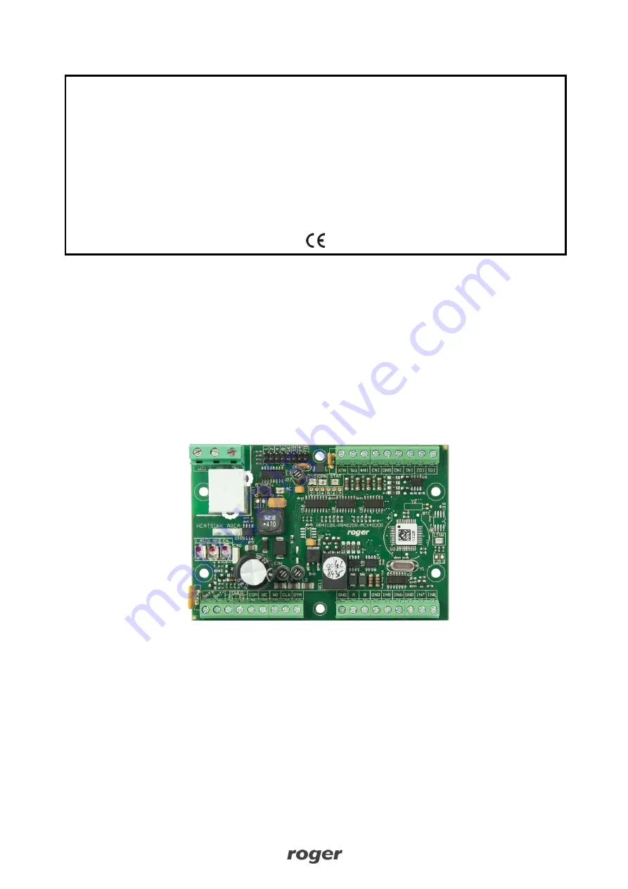
MCX402-BRD Operating Manual
Product version: 1.0
Firmware version: 1.0.4 or newer
Document version: Rev. D
Страница 1: ...Roger Access Control System MCX402 BRD Operating Manual Product version 1 0 Firmware version 1 0 4 or newer Document version Rev D ...
Страница 2: ...supplied with 12VDC but then it does not offer power supply outputs and battery charging The expander charges backup battery with 300mA stabilized current up to 13 8V Backup power supply is activated automatically in case of main powers supply shortage If the voltage at backup battery drops below approx 10V then the battery is automatically disconnected from expander and remains disconnected until...
Страница 3: ...arming mode of Alarm Zone armed disarmed OPN Green Door unlocked SYS Orange Various signalling functions including errors LINK Green Data transmission on RS485 bus Inputs Expander offers 8 inputs IN1 IN8 of NO and NC type Input types are defined within low level configuration RogerVDM Input functions are assigned within high level configuration VISO Multiple functions can be assigned to the same i...
Страница 4: ... battery P1 24VDC input power supply P2 Ground AUX 12VDC 1 0 output power supply for door lock TML 12VDC 0 2A output power supply for readers IN1 IN8 Input lines GND Ground IO1 IO2 15VDC 1A transistor output lines A B RS485 bus CLK DTA RACS CLK DTA bus NO1 COM1 NC1 30V 1 5A DC AC REL1 relay NO2 COM2 NC2 230V 5A AC REL2 relay ...
Страница 5: ...both devices must be connected with any wire 3 OPERATION SCENARIOS In typical scenario of operation MCX402 BRD expander is used to control single door by MC16 controller Depending on uploaded firmware the expander can operate with 2 Wiegand or PRT terminals In practical applications expanders are usually installed within MCX402 1 KITs The MCX402 2 KIT which is additionally equipped with PS1A modul...
Страница 6: ...MCX402 BRD Operating Manual 04 12 2020 6 13 Fig 4 Scenario of operation with MCX402 1 KITs Fig 5 Scenario of operation with MCX402 2 KIT ...
Страница 7: ...MCX402 BRD Operating Manual 04 12 2020 7 13 Fig 6 Typical door control with Wiegand readers ...
Страница 8: ...VDM program select MCX v1 x device firmware version RS485 communication channel and serial port with RUD 1 interface 3 Click Connect the program will establish connection and will automatically display Configuration tab 4 Enter unoccupied RS485 address in range of 100 115 enable Wiegand or PRT terminals configure input types e g NC for IN5 according to fig 6 and other settings according to require...
Страница 9: ...tered with keypad When set to 0 then PINs are disabled Range 0 8 Default value 4 Max PIN length Parameter defines maximal number of digits in PIN When set to 0 then PINs are disabled Range 0 8 Default value 8 key clears PIN buffer Parameter defines if already entered digits of PIN can be deleted with key Range Yes No Default value Yes Time between keys in PIN s Parameter defines max time between t...
Страница 10: ...n Wiegand terminal 1 2 is operated Range Yes No Default value Yes AF type Parameter defines authentication factor type returned by terminal Default value 16 Number 40bits AF class Parameter defines authentication factor class returned by terminal Default value 0002 EM KBD comment Parameter defines any text or comment which corresponds to the object It is later displayed in VISO program CDI comment...
Страница 11: ...ault MCX402DR WGx hex firmware is uploaded to expander PRT readers settings are available when MCX402DRx hex firmware from www roger pl is uploaded to expander Manual addressing The RS485 address of expander configured with RogerVDM is a software address Alternatively hardware RS485 address can be configured with jumpers and such address has higher priority than software address Note Each time the...
Страница 12: ...lated by RUD 1 interface and the option USB RS485 Converter 6 Select firmware file hex click Program and follow instructions on screen 7 Once the firmware is uploaded remove the FDM jumper and restart the device 8 Start Memory reset procedure 6 SPECIFICATION Table 4 Specification Supply voltage Nominal 18VAC min max range 17 22VAC Nominal 12VDC min max range 10 15VDC Nominal 24VDC min max range 22...
Страница 13: ...ct This symbol placed on a product or packaging indicates that the product should not be disposed of with other wastes as this may have a negative impact on the environment and health The user is obliged to deliver equipment to the designated collection points of electric and electronic waste For detailed information on recycling contact your local authorities waste disposal company or point of pu...