


60
Rockwell Automation Publication IASIMP-QS005H-EN-P - April 2016
Chapter 3
GuardLogix® Controllers Logic Integration
14. Review the imported rung comments on the next page to understand the general operation and configuration
details.
Refer to the GuardLogix Instruction Set Reference Manual, publication
, for additional information
and configuration of the instructions required for your application.
This Safety Logic Example should only be used and applied in accordance with the Safety Concepts and Requirements covered in the GuardLogix Controller Systems Safety Reference Manual
(Publication 1756-RM095).
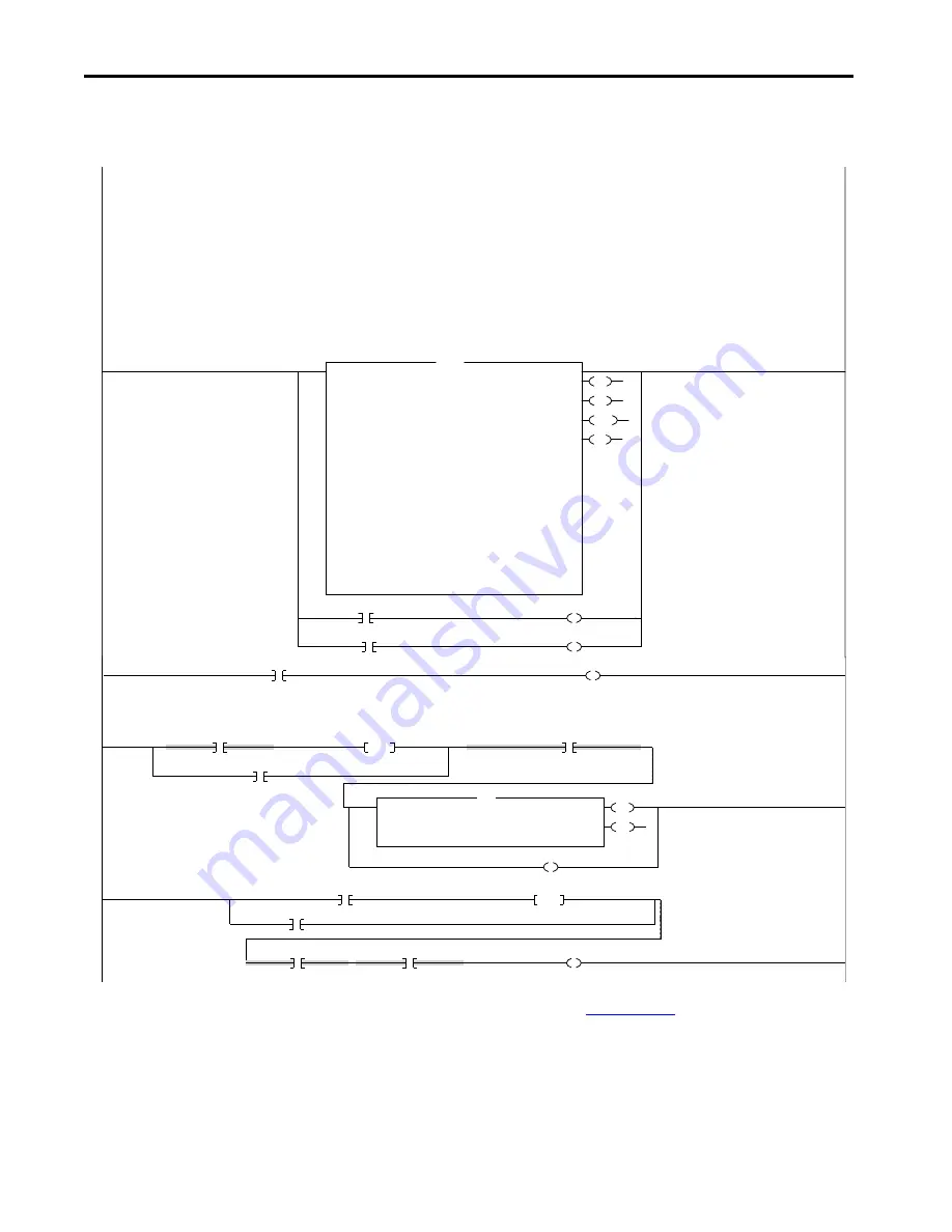
GENERAL OPERATION
The Dual-channel Input Stop with Test and Lock monitors dual-input safety devices whose main function is to stop safely. This instruction can only energize Output 1 when both safety inputs, Channel A and Channel B,
are in the active state as determined by the Input type parameter, and the correct reset actions are carried out. In addition, this instruction has the ability to monitor a locked feedback signal from a safety device and
issue a lock request to a safety device. The Unlock Request input is used to request an electromagnetic lock or unlock. However, the hazard protected by this instruction must be stoppped for the instruction to issue an
unlock command. The Lock Feedback input is used to determine whether or not the safety device is currently locked. To energize output 1, the Lock Feedback input must be ON (1) in addition to the requirements of the
DCST instruction.
CONFIGURATION DETAILS
The DCSTL instruction tag is CONTROLLER scoped, and if you wish to copy and paste this into another routine, you will need to provide a unique name on every new copy. The ZoneName_DeviceName DCSTL instruction
tag name will identify this instruction with the unique device within a specific zone. This Safety Logic Example is set to AUTOMATIC Reset Type for continuous monitoring of input device states. Using automatic reset
functionally moves the safety output reset function from the DCSTL instruction's Reset to your Safety Output Logic. The Safety Output Logic examples will illustrate this safety output reset functionality. This Example
illustrates a Locking Switch device that is wired to inputs 0 and 1 on a Guard I/O module named "ModuleName". Lock feedback is wired to input 2. Test Prompt Lamp is wired to Test Output 2 and unlock solenoid is
to Test Output 00. Reassignment of the tags will need to be made to match your unique safety wiring configuration. The Reset is assigned to a tag named "Cmd_ZoneName_FaultReset" representing a command triggered
by an HMI or hardwired input within a Safety_Output_CAT3_CAT4 Safety Logic Routine. The same Fault Reset tag "Cmd_ZoneName_FaultReset" for this DCSTL instruction will typically be used on all of the safety input
and output instructions within it's safety zone. The output from the DCSTL, ZoneName_DeviceName.O1, energizes the OTE with tag name Sts_ZoneName_DeviceName_InputOK, that is used in the input
interlock logic within the safety output device logic.
0
O1
TC
ULC
FP
Dual Channel Input Stop With Test And Lock
DCSTL
Zone1_LOCKINGSW1
Safety Function
SAFETY GATE
Input Type
EQUIVALENT - ACTIVE HIGH
Discrepancy Time (Msec)
500
Restart Type
AUTOMATIC
Cold Start Type
MANUAL
Channel A
CellGuard1:I.Pt00Data
0
Channel B
CellGuard1:I.Pt01Data
0
Test Request
Cmd_Zone1_Safety_Test
0
Unlock Request
Cmd_Zone1_LOCKINGSW1_Safety_Unlock
0
Lock Feedback
CellGuard1:I.Pt02Data
0
Hazard Stopped
LOCKINGSW1_Motion_Stopped
0
Input Status
CellGuard1:I.CombinedInputStatus
0
Reset
Cmd_Zone1_FaultReset
0
DCSTL
Zone1_LOCKINGSW1.TC
CellGuard1:O.Test02Data
*****************************Locking_Switch_CAT3_CAT4 Safety Logic *****************************
Zone1_LOCKINGSW1.ULC
CellGuard1:O.Test00Data
1
Zone1_LOCKINGSW1.O1
Sts_Zone1_DeviceName_InputOK
Locking Switch Output Solenoid Interlock Logic
The following two rungs provide the logic that energizes the Cmd_ZoneName_Unlock_Request, allowing entry into the Safety Zone, 3 seconds after the Zone’s Output has been disabled. Test Outputs
configured as standard can be used to drive the locking switch solenoids. This logic shows the output solenoid connected to a test output of a Guard I/O module, ModuleName:O.Test00Data. The test
output is used as a convenient standard output, as this solenoid may be connected to a safe or standard output. Reassignment of tags will need to be made to match your unique safety wiring configuration.
2
/
Sts_Zone1_OutputEnable
ONS
Wrk_Zone1_LOCKINGSW1_OutputEnable_ONS
Wrk_Zone1_LOCKINGSW1_EntryDelay_Latch
/
Wrk_Zone1_LOCKINGSW1_EntryDelay_Timer.DN
EN
DN
Timer On Delay
Timer
Wrk_Zone1_LOCKINGSW1_EntryDelay_Timer
Preset
3000
A
ccum
0
TON
Wrk_Zone1_LOCKINGSW1_EntryDelay_Latch
3
Wrk_Zone1_LOCKINGSW1_EntryDelay_Timer.DN
ONS
Wrk_Zone1_LOCKINGSW1_EntryDelay_Time
CellGuard1:O.Test00Data
/
Cmd_Zone1_FaultReset
/
Sts_Zone1_OutputEnable
Cmd_Zone1_LOCKINGSW1_Safety_Unlock
Содержание 1756-L71S
Страница 8: ...8 Rockwell Automation Publication IASIMP QS005H EN P April 2016 Summary of Changes Notes ...
Страница 10: ...10 Rockwell Automation Publication IASIMP QS005H EN P April 2016 Where to Start Notes ...
Страница 176: ...176 Rockwell Automation Publication IASIMP QS005H EN P April 2016 Chapter 6 Safety System Application Guide Notes ...
Страница 199: ......