Robustel R2110 Hardware Manual
RT044_HM_R2110
7/11
Interface Descriptions
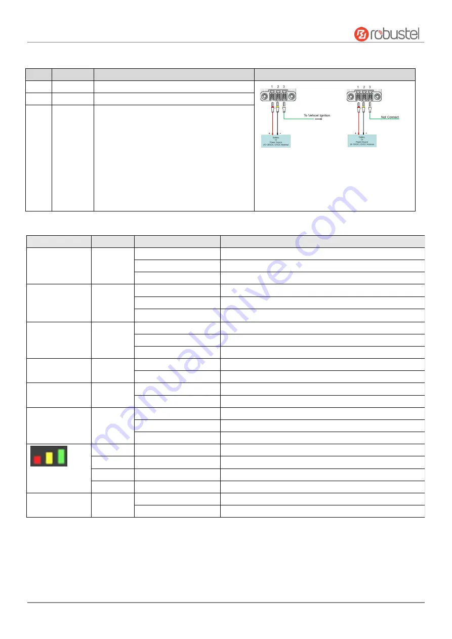
1. Power Supply.
3PIN 3.5mm pitch terminal block.
PIN
Description
Note
1
V+
Connect adapter or battery positive (red line)
With ACC Function
With POE Function
Note:
1)
ACC and POE function can only be selected one
2)
The input voltage is 10 to 30V DC(With ignition
sensing) or 9 to 36V DC(Without ignition sensing)
2
V-
Connect adapter or battery negative (yellow line)
3
ACC
(Optional)
Car ignition and flameout detection (green line)
Note: when the car ignition and flameout detection function
is not used, the ACC pin is connected to the
V+
and cannot be
left floating.
2. LED Indicator.
Name
Color
Status
Description
RUN
Green
On, solid
Router is powered on (System is initializing)
On, blinking
Router starts operating
Off
Router is powered off
MODEM
Green
On, solid
Link connection is working
On, blinking
Data is sent and received.
Off
Link connection is not working
NET
Green
On, solid
Connection to 4G network is established
On, blinking
Connection to Legacy network (3G or 2G) is established
Off
Network is not joined or joining
USR-OpenVPN
Green
On, solid
OpenVPN connection is established
Off
OpenVPN connection is not established
USR-IPsec
Green
On, solid
IPsec connection is established
Off
IPsec connection is not established
USR-SIM
Green
On, solid
Main SIM card is being used
On, blinking
Backup SIM card is being used
Off
No SIM card is being used
Green
On, solid
Received signal strength is greater than -73dBm (strong signal)
Yellow
On, solid
Received signal strength -91 to -73 dBm (moderate signal)
Red
On, solid
Received signal strength -111 to -93 dBm (weak signal)
--
Off
Very Low Signal strength (0) is available or No signal
Wi-Fi
Green
On, solid
Wi-Fi is enabled and working properly
Off
Wi-Fi is disabled or not working properly
Note:
You can choose the display type of USR LED. For more details, please refer to
RT123_SM_RobustOS Software Manual
Service > Advanced > System >System Settings > User LED Type.


