


First start-up
Installation, use and maintenance manual – Calorio M
21
5
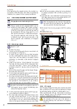
To adjust the gas-fired convector for operation with LPG,
proceed as described below.
Figure 5.1
1. Remove the casing.
2. Connect a pressure gauge to the pressure intake A, af-
ter removing its sealing screw.
3. To adjust the gas pressure, the gas-fired convector
must be switched off, then access the "advanced set-
tings menu" and the submenu "transparent control
parameters" as described in the relevant Paragraph
4. Turn the knob until the parameter P002 is displayed;
then, using the knob (press – rotate – press), change
the parameter value to 15: this activates the "valve
calibration" function (previous valve settings will be
deleted).
5. Wait until the value 20 appears on the display (the gas-
fired convector will turn on).
6. Turn the knob to display the parameter P03 "gas pres-
sure calibration at maximum power".
7. Press the knob and increase the displayed value by 1
to 5 points at a time (this operation may be repeated
several times), until the pressure gauge reads 25 mbar;
then proceed in small increments (+1) up to the re-
quired maximum pressure value (Table 5.1
Be careful not exceed the required gas pressure! If
this happens, you must repeat the calibration pro-
cedure (starting from step 4).
8. Turn the knob to display the parameter P04 "gas
pressure calibration at minimum power".
9. Press the knob and change the displayed value, start-
ing with minimal decrements (-1); press the knob
to confirm and wait for the pressure gauge read-
ing. Proceed in this way (with minimal decrements)
down to the required minimum pressure value (Table
5.1
p. 20).
10. Turn the knob until parameter P002 is displayed and
press it; this saves the new calibration settings.
11. Turn the knob and press it to set parameter P002 to
the value "0": the "valve calibration" function is deacti-
vated (the gas-fired convector will switch off).
After the adjustment, stop and start the appliance
and check that burner pressure has stabilised. If
necessary perform the adjustment again.
12. Disconnect the pressure gauge and refit the sealing
screw.
13. Replace the casing.
5.3
GAS CHANGEOVER
Paragraph reserved exclusively to TACs.
After the gas changeover, check the combustion
parameters as described in Paragraph 5.2
Check that the gas supply line is suitable for the
new fuel type used to supply the unit.
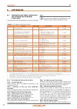
Figure 5.2
Detail of burner assembly and detail of the nozzle holder and calibrated nozzle
A Nozzle holder.
B
Cap
C
Nozzle
A
C
A
B
5.3.1
Conversion from natural gas to LPG
Figure 5.2
1. Cut off electric power and gas supply.
2. Remove the casing from the frame and disconnect the
casing grounding cable.
3. Unscrew the B plug with a no. 19 wrench.
4. Using a no.10 socket wrench introduced in the open-
ing, unscrew the nozzle holder A.


