Installation and user manual
Error! Use the Home tab to apply
Titolo 1 to the text that you want to
appear here.
25
7.1.3
Gas valve regulation
To adjust the gas valve, follow this procedure:
1.
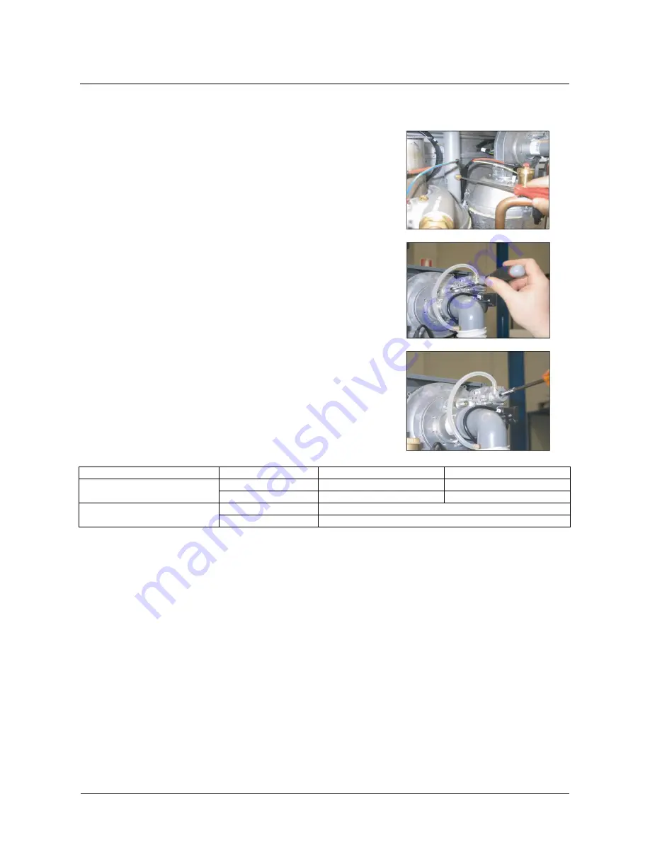
Put the flue sensor into the flue system. (Figure 35)
2.
Rotate the Venturi gas regulation screw (throttle) with two
turns on the left as shown in Figure 36.
3.
Make sure that there is a request from at least one of the
two room thermostat. If you have problems with the thermal
assembly ignition rotate on the right the regulation screw, only one
turn at time.
4.
Give the maximum power to the boiler by using the digital
control panel: you have to press at the same time S2 key
(SET/ESC) and S4 key (+) just for 5 sec. Then it’s possible to
indicate the maximum fan speed by using the S4 key (par. n°15).
All the system fans will work with this selected speed. On the first
digit on the left it’s shown the selected speed. H = maximum speed.
Other two digit will show the water flow temperature (example
T1=80°C).
5.
Regulate the combustion acting on throttle (Figure 36) until
you arrive to the nominal CO2 value shown in the below table.
NOTE. To increase the gas flow rotate on the left while to decrease
the gas flow rotate on the right.
6.
Let the boiler arrive to the maximum power and then
change, if it’s necessary, the Venturi regulation.
7.
Let the boiler arrive to the minimum power by using S5 key
(-).
8.
On left of the display it will appear a “L“ (Low= minimum
power); act on the gas regulation screw Offset (see Figure 37) to
arrive to the values present in the below table.
NOTE. To increase the gas flow rotate on the right while to
decrease the gas flow rotate on the left.
Figure 35
Figure 36
Figure 37
MODEL
GAS
MAX POWER
MIN POWER
Condensing 100
Methane
CO
2
= 9.2
– 9.4%
CO
2
= 8.3
– 8.5%
LPG
CO
2
= 10.2
– 10.4%
CO
2
= 8.6
– 8.9%
Condensing 100
(serial number 312670001)
Methane
CO
2
= 9.0%
LPG
CO
2
= 10.4%
7.2 Slave boards setting
Each slave (one for each burner) needs to be properly configured so that the Master board shall detect their
right sequence. First of all slave boards needs to be divided into blocks; the system can manage until 15
blocks made of 4 slaves each.
Ex. If 5 slaves are connected to one Master, we have 2 blocks: the first is made of 4 salves and the second
of one slave.
As a consequence, complete the following procedure to fulfil the address configuration:
1.
Locate the slave position inside each block ( ex. position1,2,3 or 4).
2.
Locate the block the slave is related to (ex. Block n°1, n°2…………till block n°15)
3.
Supply each Caldaria Condensing 100 series composing the battery.
As indicated in Figure 38, to set block address we refer to the jumper J17, while for the slaves (singles
burners) we refer to the jumper J10.
Содержание CALDARIA CONDENSING 100
Страница 38: ...Installation and user manual...


