


Installation and user manual
Error! Use the Home tab to apply
Titolo 1 to the text that you want to
appear here.
18
5.3.4
Room Thermostat connection (on/off))
Connect the high temperature system's environment thermostat to terminals no. 9 and 10 (Figure 23).
The low temperature system's thermostat shall be connected to terminals no. 11 and 12 (Figure 23).
5.3.5
External probe connection
If outside temperature regulation is to be used, the outside probe (optional) needs to be connected to
terminals no. 7 and 8 (Figure 23).
The outside probe shall be installed on an outer wall, North or North/East, at a minimum height of 2.5
metres, away from windows, door, and ventilation grids.
Never install the probe in a position exposed to the sun. If it is necessary to modify the climatic curve set,
please contact a Robur Technical Support Service.
5.3.6
Connection of an external regulation 0-10v
It is possible to use the terminals n. 13 and n. 14 (Figure 23) for an external power or set-point regulation.
The input signal is a DC voltage with a range of 0-10 V. It is important to connect the positive input to the
terminal n. 13.
5.3.7
Connection of an alarm device
A 220 V clear contact block output on the boiler's terminal strip allows to connect an outside sound or visual
alarm device, capable of highlighting any technical anomalies.
The alarm device must be connected to terminals no. 18 and 19 (Figure 23)
5.3.8
Connection of a remote control
If the remote control is to be used, it must be connected to terminals no. 15, 16, and 17 (Figure 23).
5.3.9
Emergency mode
Caldaria Condensing 100 series electronic
management system includes an operation mode
called "Emergency" mode, which can be activated in
case of malfunctioning of the Master card.
Indeed, to ensure continuous operation of the
thermal assembly, the master card can be disabled
in such a way as to have the system operate at a
default
delivery
temperature
set
by
the
Manufacturer.
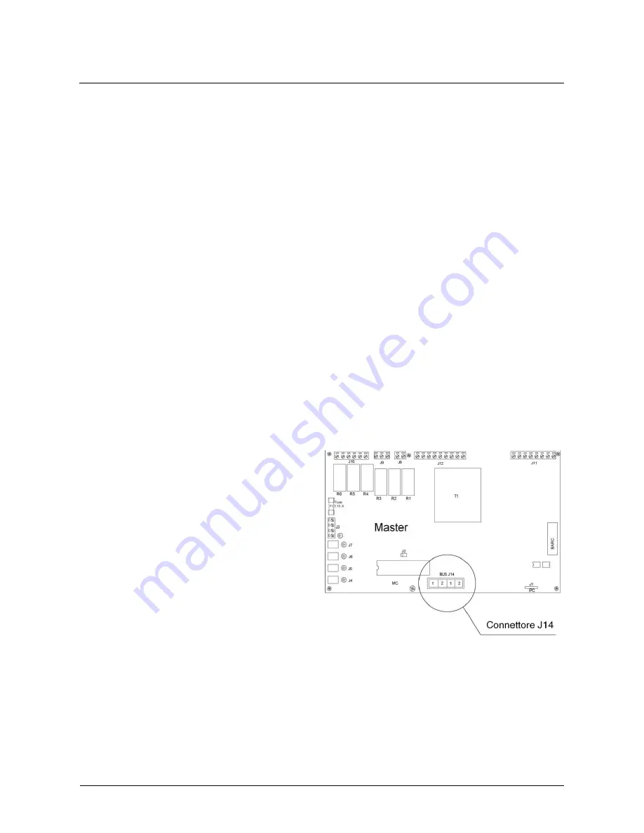
To enable the "Emergency" function, carry out the
following procedure:
a.
Disconnect the 4-pole connector J14 from
the Master card (see Figure 25);
b.
Set all four J17 switches located on each
Slave of the thermal assembly on the Off position
(Figure 26);
c.
Supply all system circulators with mains
current, using the appropriate switches;
d.
terminal X1 or terminal X2 which are part of
the cabling of the J14 connector disconnected in
point a) of this procedure must be connected to a
24V ac power supply (see Figure 27).
Figure 25
Содержание CALDARIA CONDENSING 100
Страница 38: ...Installation and user manual...


