18
Gas unit heaters
Gas unit heaters chronothermostat
Rev.: C
Cod.: D-LBR500
21MCLSDC032
28/09/2021
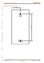
Figure 6.1
Location
150 cm
7
CONNECTING CABLES
The terminals for the electrical connections are positioned in the rear part of the chronothermostat.
Figure 7.1
Connecting cables
COM
NO
NC
8
MOUNTING
1. Drill two holes of diameter 6 mm in the wall (use the
template attached to the manual to mark the spacing
between these holes).
2. Insert plastic wall plugs (included in the kit).
3. Screw in the left screw with a 3 mm clearance.
4. Put the key-hole shaped opening in the rear wall of the
regulator over the screw head and slide it to the right.
+39 035 888111 - F +39 035 884165
w
w
w
.robur
.it
24040
Ver
dellino/Zingonia (BG) I
taly
via P
ar
ig
i 4/6
robur@r
obur
.it
Robur S.p
.A.


