background image

28 

VENTBOSS 

 SERIES 300 SPACE SAVER COLLECTORS OWNER’S MANUAL

APPENDIX A:

INSTALLATION, OPERATION & MAINTENANCE

 (continued)

Using Your VentBoss Fume Arm 

The construction guarantees a safe and reliable function without continuous servicing and 
special handling. The adjustment of the ERGO extraction arm consists mainly in corrections 
within the frictional joints. The frictional brakes are placed in each joint of the d evice and 
their function is to give the balance and self-supporting properties of the whole extraction 
arm and ensure an easy manoeuvring during the operation.

The adjustment of the frictional brakes is carried out by increasing or reducing the tension of 
the nuts upon the frictional elements. 
The brake adjustment in the following joints ought to be executed in such a way that it 
guarantees the stability and self-supporting features of the extraction arm (which is important 
to keep the stable arm position), whereas on the other hand this cannot cause any excessive 
resistance while User is changing the arm position. Having completed the adjustment, tighten 
up the counter-nut. The placement of the adjustment nuts is illustrated in the “VentBoss 
Extraction Arms – Dimensional Drawings” (Diagram 1—Appendix A).

Safety

The VentBoss extraction arms will not cause any risk provided that they are firmly and 
correctly mounted to the wall or another structural element of the building. 

CAUTION!

 Unsure installing could cause uncontrolled detachment 

of the device and be serious risk to personnel / people in the vicinity. 
Having completed the work, leave the extraction arm in the ultimate operational position, in 
case when it constitutes obstacle to personnel/User, set in into the home position.
Prior to installing check the load carrying capacity of the building structure.

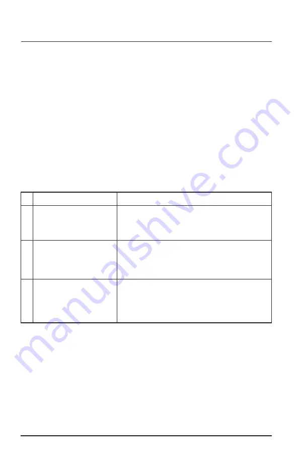
 Type

1.  The extraction arm is falling.

2.  The extraction arm is 

automatically setting always 

in the same position.

3.  Drop in the air suction rate 

along with the increased 

noise level.


Possible Reason & Corrective Action


-Improperly adjusted frictional brake.


-Increase the tension upon frictional disks of the brake 

in the joint by tightening the adjustment nuts.


-The rotation axis of the arm is not positioned vertically. 


-Carry out the positioning of the mounting flange of the 

ERGO extraction arm to set the rotation axis vertically.


-Improper impeller rotation sense of the extraction fan.


-Change the phase connection sequence (only 3-phase 

motor). If the mesh holes of the inlet net are clogged, 

clean them using a wire brush.

Содержание VentBoss 300 Series

Страница 1: ...Installation Operation Maintenance OWNER S MANUAL SERIES 300 SPACE SAVER COLLECTORS MODELS S310 S311 S312 S313 S314 S315 S316 S317 S318 S319 S320 S321 S350 ...

Страница 2: ......

Страница 3: ...4 S315 S316 S317 S318 S319 S320 S321 S350 OWNER S MANUAL Installation Operation Maintenance Manufactured by RoboVent 37900 Mound Road Sterling Heights MI 48310 USA 855 558 VENT www ventboss com 2017 RoboVent Product Group Inc All rights reserved ...

Страница 4: ...ding needs When your VentBoss needs scheduled maintenance keep in mind that VentBoss has specially trained staff in servicing our equipment We would be pleased to answer your questions and concerns you may have At VentBoss we are committed to making your shop factory a safe and healthy environment for your workers Please take time to read this manual thoroughly before installing and operating the ...

Страница 5: ...ies 300 Section 200 Page 7 8 Receiving Inspection Section 300 Page 9 Equipment Configurations Section 400 Page 10 12 Installation Section 500 Page 13 14 Operation Section 600 Page 15 16 Maintenance Section 700 Page 17 18 Troubleshooting Section 800 Page 19 Appendix A Fume Arm Installation Operation Maintenance TABLE OF CONTENTS ...

Страница 6: ...could restrict airflow Prolonged restriction could damage the motor and electrical components The mesh panels of the intake are designed to obtain uniform air distribution Any disturbance of this flow will decrease efficiency 4 Refer all service matters to qualified service personnel Repair and or servicing is required when the unit is damaged in any way such as controls supply wiring or in the ca...

Страница 7: ...net 3 Easy Access Filter System For your convenience the VentBoss Series 300 units are all designed with our proprietary SnapLock filter system which allows the filter to be removed in seconds Changing filters is a rapid and simple procedure and eliminates any need to undo nut bolts or threaded components which are particularly prone to clogging and jamming inside a dust collector cabinet 4 High G...

Страница 8: ... assembled prior to the unit being approved to ship from the VentBoss assembly plant Figure 2 6 Built In Spark Arrestance The VentBoss internal SparkOut plenum quickly extinguished sparks created through the welding or grinding process 7 Built In Pulse Cleaning A powerful back flush cleaning system delivers high pressure air into the inner core of the cartridge filter This powerful cleaning system...

Страница 9: ...le it is in transit unless specific arrangements are made otherwise Compare the number of items received against the carrier s bill of lading Inspect all items for apparent damage Immediately report any shortages or obvious damage to the carrier and to your local VentBoss Representative call the factory at 1 855 558 VENT or email customer service ventboss com When all skids are completely unpacked...

Страница 10: ...rea where welding is performed The S310 includes a standard intake The S311 includes an 8 diameter by 10 externally articulated fume arm with hood The S312 includes an 8 diameter by 14 externally articulated fume arm with hood The S313 includes two 6 diameter by 10 externally articulated fume arms with hoods The S314 includes two 6 diameter by 14 externally articulated fume arms with hoods Easily ...

Страница 11: ... S318 and S319 can be wall mounted or hung from the roof or overhead structure The S315 includes a standard intake The S316 includes an 8 diameter by 10 externally articulated fume arm with hood The S317 includes an 8 diameter by 14 externally articulated fume arm with hood The S318 includes two 6 diameter by 10 externally articulated fume arms with hoods The S319 includes two 6 diameter by 14 ext...

Страница 12: ...20 and S321 operate on a Back Draft principle They can potentially draw the smoke from as far as 30 away from the worker as shown in the diagram The smoke is then filtered through the high efficiency Nanofiber MERV15 cartridge filter and returns clean air to the plant The S320 is configured to stand on the floor and sit on 3 x 6 tubular legs that double as fork pockets The S321 can be wall or ceil...

Страница 13: ...running in reverse air will still be drawn through but at a fraction of the designed volume and will produce excessive noise and potentially vibration To correct this reverse rotation of the blower wheel swap the terminal attachment position on 2 of the 3 phase wires connected to the Disconnect Amperage requirements of all models are found in the Equipment Specifications Sheets Compressed Air Hook...

Страница 14: ...racket A to cabinet in two places using 1 2 20 UNF 1 hex bolts E 3 Attach bottom cabinet hanging bracket C to cabinet in four places using 3 8 16 UNC 1 5 hex head tapping screws D 4 Place cabinet on wall mount and anchor bottom two holes on cabinet hanging bracket C to wall using concrete anchors I and 3 8 16 UNC 1 hex bolts H 5 Use 3 8 washers F and 3 8 16 UNC 0 75 hex bolts G to secure cabinet b...

Страница 15: ...gure 7 5 15 times to back flush the filter cartridge leaving sufficient time for the air tank to recharge between each press This cleaning process will loosen the collected particulate from the cleaning cartridge and will be collected in the tray below Best results will be achieved when the motor is turned off for this process Fume Arm Adjustment for models with Fume Arms The Multi Positional Fume...

Страница 16: ...and at the first hinge point can be tightened or loosened with a 7 8 wrench Figure 9 Simply tighten the nut on the friction disk to make the joint stiffer or loosen to give the joint freer less restricted action Be careful not to over tighten the disk as this could cause permanent injury to the arm Some fume arms come equipped with a shock or strut The shock is not adjustable Figure 10 For more in...

Страница 17: ...ingle action lever To Replace the filter cartridge open the filter access door and pull up on the two SnapLock levers Figure 11 releasing the filter cartridge Now the filter can be removed Figure 12 Reload the new Cartridge Filter into the Filter Cabinet Ensure filters are aligned correctly in the SnapLock rails to give an air tight seal when the gasket is compressed Engage the SnapLock by pushing...

Страница 18: ... located immediately below the cartridge filter and can be accessed through the filter door Cleaning frequency of the dust bin will vary depending on the welding situation and use Periodically check the bin for particulate When 2 3 inches of dust forms at the bottom of the bin remove with a vacuum or brush and pan Figure 14 Blower Maintenance The motor and blower in your VentBoss Series 300 unit w...

Страница 19: ... suction across intake Check the following 1 Cartridge filter is loaded Review Pulsing the VentBoss Series 300 Collector in Section 600 under OPERATION With the air hooked up press the Solenoid Plunger 25 30 times with a 3 5 second spacing between each pulse Make sure the unit is turned off for this process 2 If using a fume arm make sure the butterfly valve behind the intake hood is not closed So...

Страница 20: ......

Страница 21: ...APPENDIX A FUME ARM INSTALLATION OPERATION MAINTENANCE ...

Страница 22: ...ior to installing check the load capacity of the wall or other building structure where the device shall be mounted F The devices cannot be applied for conveying the air containing aggressive contaminants Structure Function VentBoss extraction arms are constructed of subsequent assemblies presented in Diagram 1 See Appendix A Swivel Two pipe segments I and II connected together with frictional joi...

Страница 23: ...the RO type extension arm Technical Specifications Type Dimensions Weight Dn inch L inch A inch B inch C inch ERGO L Z 2 X 90 80 35 71 22 91 X 37 4 ERGO L Z 3 X 90 80 35 71 22 91 X 37 4 ERGO L Z 4 X 90 80 35 71 22 91 X 37 4 ERGO D Z 2 X 90 80 35 71 22 91 X 37 4 ERGO D Z 3 X 90 80 35 71 22 91 X 37 4 ERGO D Z 4 X 90 80 35 71 22 91 X 37 4 Refer to diagrams below for DN L A B C VentBoss extraction arm...

Страница 24: ...lower joint see detail B Pic 2 4 Fold in the loose fabric edge at the end of the hose then sleeve the hose onto the swivel ferrule and secure it with a hose clamp 5 Fasten the termination of the gas spring with a screw to the plate of the lower joint see detail A Pic 1 6 Connect the upper segment II with the lower segment I using a hose following the point 4 7 Screw up the outer joint to the hood ...

Страница 25: ...case when the extraction arm is installed on a wall bracket it is important to carry out levelling of the bracket surface while mounting it on a wall If the bracket is not levelled the extraction arm is likely not to keep the requested by User work position and tend to fall into one position only Pic 4 Pic 1 Pic 2 Pic 3 ...

Страница 26: ... it is important to bring the device into completely assembled state according to the enclosed instruction The extraction arms can be mounted on a wall bracket delivery on separate order The diameter and placement of the mounting holes in the bracket and in the arm swivel are the same It is inadmissible to install the VentBoss extraction arm directly to the ventilation installation as it is usuall...

Страница 27: ...n gas shield CO2 argon It is important that the hood is effectively capturing the fume and does not cause any obstacle to User Using the shut off damper lever adjust the intake air volume to eliminate the dust fume most efficiently The position of the hood and the damper lever can be changed many times during the work so User can adjust them most appropriately to the current needs After the work i...

Страница 28: ... in the VentBoss Extraction Arms Dimensional Drawings Diagram 1 Appendix A Safety The VentBoss extraction arms will not cause any risk provided that they are firmly and correctly mounted to the wall or another structural element of the building CAUTION Unsure installing could cause uncontrolled detachment of the device and be serious risk to personnel people in the vicinity Having completed the wo...

Страница 29: ...tional intensity It is recommended to examine the pollution state of the discharge conduits once in three months Transportation Storage VentBoss extraction arms have to be stored and transported in partly disassembled state and in special packages The devices ought to be stored in dry and well ventilated rooms During the transport reloading protect the device from scratching indents and pay attent...

Страница 30: ...1600 1800 2000 2200 2400 0 100 200 300 400 500 600 0 200 400 600 800 1000 1200 1400 1600 1800 2000 2200 2400 0 100 2 ERGO L Z 0 200 400 600 800 1000 1200 1400 1600 1800 2000 0 200 400 600 800 1000 1200 1400 1600 1800 2000 2200 2400 0 200 400 600 800 1000 1200 1400 1600 1800 0 200 400 Type D mm E mm F mm L mm ERGO L Z 2 65 51 79 72 28 27 90 79 ERGO L Z 3 87 56 108 07 38 74 122 28 ERGO L Z 4 106 06 ...

Страница 31: ... D Z flow m h Volume flow m h flow m h Volume flow m h Flow resistance Pa me flow m h 500 600 0 200 400 600 800 0 100 200 300 400 500 600 700 800 900 1000 1100 0 2000 2200 2400 0 200 400 600 800 1000 1200 1400 1600 1800 0 200 400 600 800 1000 1200 1400 1600 1800 2000 2200 2400 2600 Hood with light Inlet Flange Inlet Side Plate Inlet Side Housing Blower Wheel Drive Side Housing Motor ...

Страница 32: ... 2017 RoboVent 37900 MOUND ROAD STERLING HEIGHTS MICHIGAN 48310 USA 855 558 VENT WWW VENTBOSS COM ...

Отзывы: