12/18/2017
U2D2
http://support.robotis.com/en/product/auxdevice/interface/u2d2.htm
5/6
1. RoboPlus
RoboPlus supports Windows environment to manage controllers and DYNAMIXELs.
A.
: R+ Task 2.0 can be used when downloading Task Code to the controller.
B.
: R+ Motion 2.0 can be used when downloading Motion file to the controller.
: R+ Manager 2.0 is used to connect controllers or DYNAMIXELs and update firmware or test the control table..
)
2. Dynamixel Workbench
Dynamixel Workbench supports Linux environment to test control table of DYNAMIXEL.
ROBOTIS GitHub (
https://github.com/ROBOTIS-GIT
)
3. Dynamixel SDK
Dynamixel SDK supports various programming languages such as C, C++, C#, MATLAB, LabVIEW, Python and Java in order to help developing
DYNAMIXEL control software. Dynamixel SDK provides a bundle of functions/methods that can be used for operating DYNAMIXEL with protocols in
the form of digital packet. Dynamixel SDK is free to download from GitHub.
ROBOTIS GitHub (
https://github.com/ROBOTIS-GIT
)
Additional Features
1. Internal DIP Switch
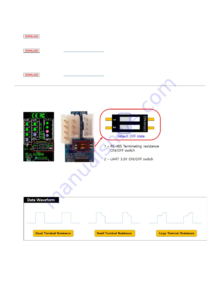
There is a two-pole switch inside of the plastic cover. This switch is set to OFF as a default. Under normal circumstances this default setting is
recommended, therefore, the switch cannot be accessed without opening the case. Please open the case and set RS-485 termination resistor and
UART 3.3V power switch only after thoroughly understand its usage
A. RS-485 Termination Resistor
(120Ω) Switch
T
ransmission devices are designed to have certain impedances based on design standard and signal reflection or interference can occur when
impedance do not match over the transmission lines. The termination resistors at the end of transmission lines suppress such effect by adjusting
impedance and allowing constant current flow. However, the termination resistor is not a mandatory, especially in a short RS-485 network with lower
communication baud rate.
If communication is suffering from frequent errors, the termination resistor might be required. The regular 120Ω termination resistor will be applied on
the transmission line by shifting the switch to ON. If termination resistor doesn’t resolve the communication issue, the resistance value might need to
be adjusted.
B. UART 3.3V Power Supply Switch
The peripheral device such as controllers that can be connected to the 4Pin UART usually have an external power source, therefore additional 3.3V
power from the UART port #2 pin is not necessary.
However, when connecting BT-410 that does not have an external power source needs to be powered by the 4Pin UART port #2 pin. In this case, the
UART 3.3V power switch need to be turned on.
If the switch is turned on, second pin of the 4Pin UART connector will be able to supply 3.3V.


