background image


Beginner Level Robot Series

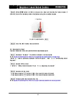
  Step  5    When  START  button  of  CM-5  is  pressed,  the  robot  will  look  like  the  figures  below.  If 

different, check the assembly points of Dynamixel using the assembly diagram.. 

※  Top View 

※  Side View 


  Step 6    Close the CM-5 online robot activation. 


(4) Operating the Robot 

Operate completed robot using demonstration(example)program. 


  Step 1    Download “Example”  file which is behavior control program. 

(In CD, 

Applied Robots\Beginner\Pan Tilt\DemoExample(Pan Tilt).bpg

※Refer  to  “How  to  download  Behavior  Control  Program”  from  “2-1-2  Downloading  Robot 

Programs.”. 


  Step 2    Operate offline robot. 

※  Refer to “Offline Robot Activation”from “2-1-3. Operating the Robots” 

  Step 3    Operation of the robot 

- If you keep pressing    U    button of CM-5, the tilt joint moves upward. 

- If you keep pressing    D    button of CM-5, the tilt joint moves downward 

- If you keep pressing    R    button of CM-5, the pan joint rotates to the right. 

- If you keep pressing    L    button of CM-5, the pan joint rotates to the left 


  Step 4    Compare with the provided video clip 

(In CD, 

Applied Robots\Beginner\Pan Tilt \DemoExample(Pan Tilt).wmv


The Pan Tilt is perpendicular to    CM-5     

The Pan Tilt is parallel to    CM-5     

41

Содержание Beginner level robot series

Страница 1: ...v1 0 Closer to Real ROBOTIS CO LTD www robotis com Bioloid QuickStart Beginner Level Robot Series ...

Страница 2: ... 16 2 2 Examples of Beginner Level 18 2 2 1 Crossing Gate 19 2 2 2 Universal Gauge 24 2 2 3 Sound Level Meter 28 2 2 4 Crocodile Mouth 32 2 2 5 Pan Tilt 37 2 2 6 Parking Gate 42 2 2 7 Melody Car 47 2 2 8 Robot Arm 52 2 2 9 Obstacle Detection Car 57 2 2 10 Greeting Penguin 62 2 2 11 Attacking Duck 68 2 2 12 Cliff Detection Car 73 2 2 13 Clapping Penguin 78 2 2 14 Walking Droid 84 3 Bioloid Operatio...

Страница 3: ...Beginner Level Robot Series 1 Starting Bioloid 3 ...

Страница 4: ... to PC allowing them to program the robots With the instruction guides that clearly explain the details of assembling the robots and with the downloadable materials that will further help users the users can create the robots in any styles they choose Users can easily assemble various robots as it consists of many blocks of different shapes QuickStart book explains how to assemble various robots s...

Страница 5: ... functions as joint of robot It is a two way Bilateral communication servo driven by network and has endless turn mode AX S1 Robot Exclusive Sensor Module Dynamixel AX S1 Dynamixel sensor module AX S1 consists of three pairs of sensors that detect distance brightness and heat It also has many other fuctions such as sounds detector remocon transceiver and sound buzzer as well Frame Cable Bolt Nut A...

Страница 6: ...each part of AX 12 Acutator LED Connector ID Names of each part of AX S1 Sensor Module Sensor ID Connector Names of each part of CM 5 POWER POWER JACK Serial Cable Jack START button MODE button U button L button D button R button ON OFF 6 ...

Страница 7: ...and video clips for Bioloid robots Robot program sources that are explained in the User s Guide Help documents and video clips that assist in operating Bioloid robots 1 3 2 Installing Software The CD will execute autorun when the users put the CD inside If the automatic setup does not initialize go to Software Setup exe and setup the program manually When the setup is finished Robot Terminal Motio...

Страница 8: ... mastered the users can assemble robots in any styles that they like The User s Guide PDF document is included in the CD AX 12 Manual This manual is generally referred by the experts in the field If the users want to know the advance functions of AX 12 they can check out this manual It is a PDF document and it is included in the CD AX S1 Manual This manual is generally referred by the experts in t...

Страница 9: ... Robots Beginner kit Beginner kit AX 12 4 pcs Comprehensive kit OR Beginner kit AX 12 14 pcs F r a m e s e t Beginner Level Robots Robots with 4 and less joints that can be assembled with Beginner kit Advenced Level Robots Robot with 18 and less joints that can be assembled with Comprehensive kit If you want to assemble advanced level with Biginner kit You need to purchas frame set and Dynamixels ...

Страница 10: ...Beginner Level Robot Series 2 Assembling Bioloid 10 ...

Страница 11: ...loading Robot Programs Operating the Robots 2 1 1 Assembling the Robots Assemble the robots in orderly refer to assembly map in QuickStart Step 2 Step 3 Assembling the Robots Example Easy instruction to insert nuts for AX 12 refer to Help Files Inserting nuts for AX 12 wmv video clip In CD 11 ...

Страница 12: ...oints it is difficult to manage the robot s movement with the behavior control program only Motion data was added to control the multi joints movements of the robot additionally Behavior control program is necessary allthe time when you activate the robot but motion data does not essentially need Download Program Serial Cable If your PC does not support Serial COM Port install USB2Serial converter...

Страница 13: ... menu Click Download button Serial Cable When download is complete progress bar color changes and download button changes to complete OFF Close the download dialog box Execute Behavior Control Programmer it doesn t need when a program already executed Go to File F Select Open o menu and open the behavior control program you want If problem occurs in this progress above formality refre to Download ...

Страница 14: ...d open the motion data file you want ON Connect PC and CM 5 Serial Cable OFF If problem occurs in this progress above formality refre to Download Troubleshooting from page 2 1 2 Downloading Robot Programs Turn on Power of CM 5 Execute Behavior Control Programmer If it has done previously not necessary When download is complete progress bar color changes Download is completed Select Management M Ro...

Страница 15: ...from 3 Bioloid Operation and Maintenance Troubleshooting Step 1 Make sure CM 5 is connected to the PC Troubleshooting Step 2 Make sure CM 5 power is on Types of Error Message Troubleshooting Step 4 Set up correct communication port number After setting up correct communication port number try the connection again by clicking Connect CM 5 Troubleshooting Step 3 Close the programs that are using the...

Страница 16: ...of the robots without the connection to PC Press MODE button to make PLAY LED flash on and off Whenever MODE button is pressed LED will be on in the order When START button is pressed program is executed When program is executed the LED no longer flashes on and off but it is still turned on Disconnect Serial Cable from CM 5 Serial Cable 16 ...

Страница 17: ... Behavior Control Programmer If it has done previously not necessary Click Play to start to program Click the stop to finish the program ON Connect PC and CM 5 Turn on Power of CM 5 Click Close to close the download dialog box Serial Cable OFF Select Program P Download D menu You can check the output message from download robot program If problem occurs in this progress above formality refre to Do...

Страница 18: ... Level 1 Crossing Gate 2 Universal Gauge 8 Robot Arm 9 Cliff Detection Car 3 Sound Level Meter 10 Greeting Penguin 4 Crocodile Mouth 11 Attacking Duck 5 Pan Tilt 6 Parking Gate 13 Clapping Penguin 14 Waking Droid 7 Melody Car 12 Obstacle Detection Car 18 ...

Страница 19: ...loses with a button 1 Necessary parts CM 5 ADAPTOR CM5 motor 1 AX 12 1 CABLE 14 1 F2 1 F3 5 F6 1 BU 1 WA 1 N1 24 S1 20 S2 8 Nuts screws and cables shown below are the same as the actual size Place and measure the parts against the below illustration to choose the correct assembly part S B 1 19 ...

Страница 20: ...APTOR CM5 CM5 Step 1 4pcs 4pcs S1 N1 Battery included Step 2 Joint 2pcs F3 4pcs S1 N1 4pcs Step 3 Bar F2 8pcs S2 F6 8pcs N1 3pcs F3 Step 1 Step 2 Check assembly point motor 1 Step 4 Whole Body Assembly WA Insert nuts 8pcs N1 S B BU Step 3 12pcs S1 20 ...

Страница 21: ...Beginner Level Robot Series CABLE 14 CM 5 1 m otor 1 CABLE 14 Wiring Wiring and Completion Step 5 1 motor 1 Using side connector of connect cable CM 5 Connector 1 21 ...

Страница 22: ...te online robot Refer to Online Robot Activation from 2 1 3 Operating the Robots Step 3 Compare the execution screen with the image below If different check Dynamixel ID and cable wiring using the assembly diagram comparison part Step 4 Whenever U button of CM 5 is pressed Dynamixel LED will be on in the order shown below By pressing U button of CM 5 in order compare the Dynamixel location of the ...

Страница 23: ...wnload Example file which is behavior control program In CD Applied Robots Beginner Crossing Gate DemoExample Crossing Gate bpg Refer to How to download Behavior Control Program from 2 1 2 Downloading Robot Programs Step 2 Operate offline robot Refer to Offline Robot Activation from 2 1 3 Operating the Robots Step 3 Operation of the robot When you press U button of CM 5 the Crossing Gate opens Whe...

Страница 24: ...l the movement speed of gauge with buttons 1 Necessary parts CM 5 ADAPTOR CM5 motor 2 AX 12 1 F3 3 F6 1 N1 16 S1 18 CABLE 14 1 S2 2 Nuts screws and cables shown below are the same as the actual size Place and measure the parts against the below illustration to choose the correct assembly part 24 ...

Страница 25: ...F3 Check assembly point Step 1 Step 3 Step 2 Insert nuts Whole Body Assembly Step 4 m otor 2 8pcs S1 12pcs N1 CM 5 Step 1 CM 5 ADAPTOR CM5 Battery included 4pcs 4pcs S1 N1 Step 5 Wiring and Completion motor 2 Wiring m otor 1 CABLE 14 CM 5 2 CABLE 14 1 Using side connector of connect cable 1 CM 5 Connector 25 ...

Страница 26: ...rate online robot Refer to Online Robot Activation from 2 1 3 Operating the Robots Step 3 Compare the execution screen with the image below If different check Dynamixel ID and cable wiring using the assembly diagram comparison part Step 4 Whenever U button of CM 5 is pressed Dynamixel LED will be on in the order shown below By pressing U button of CM 5 in order compare the Dynamixel location of th...

Страница 27: ... file which is behavior control program In CD Applied Robots Beginner Universal Guage DemoExample Universal Guage bpg Refer to How to download Behavior Control Program from 2 1 2 Downloading Robot Programs Step 2 Operate offline robot Refer to Offline Robot Activation from 2 1 3 Operating the Robots Step 3 Operation of the robot If you keep pressing U button of CM 5 the speed of gauge increases If...

Страница 28: ... level in a gauge when a sensor detects sound 1 Necessary parts CM 5 ADAPTOR CM5 motor 1 AX 12 1 AX S1 F3 5 F6 1 N1 28 S1 30 CABLE 14 2 S2 2 Nuts screws and cables shown below are the same as the actual size Place and measure the parts against the below illustration to choose the correct assembly part 28 ...

Страница 29: ...ery included 2PCS Whole Body Assembly Step 5 Insert Nuts Check assembly point motor 1 N1 8pcs N1 8pcs S1 20pcs Step 2 Step 4 Step 1 Step 3 S1 4pcs 4pcs N1 F3 2pcs Step 4 Bar F6 S2 2pcs N1 2pcs F3 CABLE 14 2 Wiring Step 5 CABLE 14 CM 5 1 m otor 1 CABLE 14 Wiring 2 m otor 1 CABLE 14 Connector Using side connector of CM 5 1 connect cable 1 29 ...

Страница 30: ...perate online robot Refer to Online Robot Activation from 2 1 3 Operating the Robots Step 3 Compare the execution screen with the image below If different check Dynamixel ID and cable wiring using the assembly diagram comparison part Step 4 Whenever U button of CM 5 is pressed Dynamixel LED will be on in the order shown below By pressing U button of CM 5 in order compare the Dynamixel location of ...

Страница 31: ...Step 1 Download Example file which is behavior control program In CD Applied Robots Beginner Sound Level Meter DemoExample Sound Level Meter bpg Refer to How to download Behavior Control Program from 2 1 2 Downloading Robot Programs Step 2 Operate offline robot Refer to Offline Robot Activation from 2 1 3 Operating the Robots Step 3 Operation of the robot When you make a sound on the sensor the ga...

Страница 32: ...not detected by a sensor in front for a certain period of time 1 Necessary parts CM 5 ADAPTOR CM5 motor 3 AX 12 1 AX S1 F3 1 F6 1 N1 24 S1 18 S B 1 BU 1 WA 1 CABLE 18 1 F1 1 S2 10 CABLE 10 1 S3 4 F8 2 F10 2 Nuts screws and cables shown below are the same as the actual size Place and measure the parts against the below illustration to choose the correct assembly part 32 ...

Страница 33: ... F10 F1 F8 S2 F6 Whole Body Assembly Step 5 Check assembly point Insert nuts Step 1 N1 4pcs S1 8pcs S B BU WA Step 3 Step 4 Head Step 2 S2 6pcs 2pcs F10 N1 F8 ADAPTOR CM5 Step 1 CM 5 CM 5 Battery included 4pcs N1 4pcs S1 Step 3 Mouth 1 Step 2 Insert nuts motor 3 S1 6pcs 6pcs N1 33 ...

Страница 34: ...Beginner Level Robot Series Step 6 Wiring and Completion CM 5 1 m otor 3 CABLE 18 Wiring m otor 3 CABLE 10 CABLE 18 2 1 motor 3 2 CABLE 10 34 ...

Страница 35: ...rate online robot Refer to Online Robot Activation from 2 1 3 Operating the Robots Step 3 Compare the execution screen with the image below If different check Dynamixel ID and cable wiring using the assembly diagram comparison part Step 4 Whenever U button of CM 5 is pressed Dynamixel LED will be on in the order shown below By pressing U button of CM 5 in order compare the Dynamixel location of th...

Страница 36: ...inner Crocodile Mouth DemoExample Crocodile Mouth bpg Refer to How to download Behavior Control Program from 2 1 2 Downloading Robot Programs Step 2 Operate offline robot Refer to Offline Robot Activation from 2 1 3 Operating the Robots Step 3 Operation of the robot When you place a hand on the front of the sensor it opens the mouth and when you remove your hand it closes If there is an object ins...

Страница 37: ...ht and left and tilt up and down buttons 1 Necessary parts CM 5 ADAPTOR CM5 AX 12 2 F3 3 N1 20 S1 28 S B 1 BU 1 WA 1 CABLE 14 2 F2 1 motor 4 motor 3 Nuts screws and cables shown below are the same as the actual size Place and measure the parts against the below illustration to choose the correct assembly part 37 ...

Страница 38: ...DAPTOR CM5 Joint 1 Step 2 2pcs F3 4pcs S1 4pcs N1 F3 Joint 2 Step 3 Check assembly point S1 motor 3 4pcs S B Joint 3 Step 4 motor 4 4pcs F2 WA S1 BU Check assembly point Whole Body Assembly Step 5 Insesrt nuts motor 4 Step 4 Step 3 Step 1 Step 2 Insert nuts 12pcs N1 8pcs N1 4pcs motor 3 S1 38 ...

Страница 39: ...ner Level Robot Series connect cable CM 5 1 m otor 3 CABLE 14 Wiring 1 2 motor 3 CABLE 14 2 m otor 4 motor 4 motor 3 CABLE 14 CABLE 14 Using side connector of CM 5 1 Connector Step 6 Wiring and Completion 39 ...

Страница 40: ... to Online Robot Activation from 2 1 3 Operating the Robots Step 3 Compare the execution screen with the image below If different check Dynamixel ID and cable wiring using the assembly diagram comparison part Step 4 Whenever U button of CM 5 is pressed Dynamixel LED will be on in the order shown below By pressing U button of CM 5 in order compare the Dynamixel location of the robot with the figure...

Страница 41: ...fer to How to download Behavior Control Program from 2 1 2 Downloading Robot Programs Step 2 Operate offline robot Refer to Offline Robot Activation from 2 1 3 Operating the Robots Step 3 Operation of the robot If you keep pressing U button of CM 5 the tilt joint moves upward If you keep pressing D button of CM 5 the tilt joint moves downward If you keep pressing R button of CM 5 the pan joint rot...

Страница 42: ...door when a sensor detects an object 1 Necessary parts CM 5 ADAPTOR CM5 motor 1 AX 12 2 AX S1 F3 8 F6 1 N1 36 S1 38 CABLE 14 1 S2 6 CABLE 10 2 motor 2 Nuts screws and cables shown below are the same as the actual size Place and measure the parts against the below illustration to choose the correct assembly part 42 ...

Страница 43: ...assembly point Joint Step 2 4pcs motor 1 S1 F3 ADAPTOR CM5 Step 1 CM 5 Battery included CM 5 4pcs N1 4pcs S1 Joint 1 Step 4 F3 2pcs S1 2pcs N1 2pcs Insert nuts Whole Body Assembly Step 6 motor 1 motor 2 N1 8pcs 8pcs S1 20pcs Step 4 Insert nuts 4pcs Step 2 Step 1 N1 Step 3 Step 5 N1 Joint 2 Step 5 F3 2pcs S1 4pcs N1 4pcs 43 ...

Страница 44: ...s CABLE 14 Wiring and Completion Step 7 motor 1 motor 2 CABLE 10 CABLE 10 1 2 3 1 CM 5 m otor 1 Wiring 2 m otor 1 CABLE 14 CM 5 3 CABLE 10 m otor 2 CABLE 10 Using side connectors of connect cables CM 5 Connector Connector 1 3 44 ...

Страница 45: ...r to Online Robot Activation from 2 1 3 Operating the Robots Step 3 Compare the execution screen with the image below If different check Dynamixel ID and cable wiring using the assembly diagram comparison part Step 4 Whenever U button of CM 5 is pressed Dynamixel LED will be on in the order shown below By pressing U button of CM 5 in order compare the Dynamixel location of the robot with the figur...

Страница 46: ... In CD Applied Robots Beginner Parking Gate DemoExample Parking Gate bpg Refer to How to download Behavior Control Program from 2 1 2 Downloading Robot Programs Step 2 Operate offline robot Refer to Offline Robot Activation from 2 1 3 Operating the Robots Step 3 Operation of the robot When the sensor detects an object the crossing bar opens vertically When the sensor detects an object and the cros...

Страница 47: ...utton 1 Necessary parts CM 5 ADAPTOR CM5 motor 1 AX 12 4 motor 2 motor 3 motor 4 AX S1 F3 6 F13 4 F14 4 N1 48 S1 48 S2 16 CABLE 10 CABLE 14 2 1 Sticker 10 CABLE 6 2 Nuts screws and cables shown below are the same as the actual size Place and measure the parts against the below illustration to choose the correct assembly part 47 ...

Страница 48: ...off S1 4pcs N1 4pcs S2 4pcs N1 4pcs Assemble 2 sets using and F3 motor 1 motor 3 Insert nuts Attach nut stickers motor 3 motor 1 Right Wheel 2 sets Step 2 Sticker 2pcs Assemble taking note of the inserted location of nuts F14 F13 Make sure nuts do not come off N1 4pcs N1 4pcs S1 4pcs S2 4pcs Joint Step 3 F3 2pcs N1 4pcs S1 4pcs ADAPTOR CM5 Insert nuts Attach nut stickers Head Step 4 Step 3 Sticker...

Страница 49: ... 4 Whole Body Assembly and Wiring Step 5 motor 1 motor 3 motor 2 1 CABLE 6 2 3 4 5 CABLE 10 CABLE 10 CABLE 6 CABLE 14 Bottom view Wiring m otor m otor 1 2 m otor 2 m otor m otor 1 3 m otor m otor 3 4 m otor CM 5 4 CABLE 10 16pcs S1 Check screw assembly point Step 6 Completion CM 5 4pcs S1 Using side connector of CM 5 connect cable 5 5 connector Battery included 49 ...

Страница 50: ...om 2 1 3 Operating the Robots Step 3 Compare the execution screen with the image below If different check Dynamixel ID and cable wiring using the assembly diagram Comparison part Step 4 Whenever U button of CM 5 is pressed Dynamixel LED will be on in the order shown below By pressing U button of CM 5 in order compare the Dynamixel location of the robot with the figure Whenever U button is pressed ...

Страница 51: ...ms Step 2 Operate offline robot Refer to Offline Robot Activation from 2 1 3 Operating the Robots Step 3 Operation of the robot When you press L button of CM 5 the Melody Car chimes and moves forward at a set distance When you press R button of CM 5 the Melody Car chimes and moves backward at a set distance When you press U button of CM 5 the Melody Car chimes and turn to the right When you press ...

Страница 52: ... Necessary parts CM 5 ADAPTOR CM5 motor 1 AX 12 3 motor 2 motor 3 F1 1 F3 4 F9 1 F11 1 N1 36 S1 48 S B 2 BU 2 WA 2 CABLE 10 CABLE 14 1 2 F2 1 Nuts screws and cables shown below are the same as the actual size Place and measure the parts against the below illustration to choose the correct assembly part 52 ...

Страница 53: ... Hand Step 5 F11 F9 F3 S1 8pcs N1 8pcs CM 5 ADAPTOR CM5 Step 1 CM 5 4pcs S1 4pcs N1 Battery included F3 F2 Joint 3 Step 4 N1 4pcs S1 4pcs Step 2 Insert nuts Whole Body Assembly Step 6 Check assembly point S1 24pcs 2pcs 2pcs WA 2pcs Step 4 12pcs motor 2 motor 3 Step 3 N1 4pcs BU S B Step 5 Step 1 N1 Check assembly point Insert nuts 53 ...

Страница 54: ... Complete Wiring and Assembly Step 7 CABLE 14 CABLE 14 CABLE 10 2 3 motor 1 motor 2 motor 3 Left side view Using side connector of CM 5 1 connector 1 CM 5 1 CABLE 14 Wiring 2 m otor 1 CABLE 14 CABLE 10 m otor 1 3 m otor 3 m otor 2 m otor 2 54 ...

Страница 55: ...t Activation from 2 1 3 Operating the Robots Step 3 Compare the execution screen with the image below If different check Dynamixel ID and cable wiring using the assembly diagram comparison part Step 4 Whenever U button of CM 5 is pressed Dynamixel LED will be on in the order shown below By pressing U button of CM 5 in order compare the Dynamixel location of the robot with the figure Whenever U but...

Страница 56: ... control program In CD Applied Robots Beginner Robot Arm DemoExample Robot Arm bpg Refer to How to download Behavior Control Program from 2 1 2 Downloading Robot Programs Step 2 Operate offline robot Refer to Offline Robot Activation from 2 1 3 Operating the Robots Step 3 Operation of the robot When you press R button of CM 5 the Robot Arm rotates to the right When you press L button of CM 5 the R...

Страница 57: ...le automatically 1 Necessary parts CM 5 ADAPTOR CM5 motor 1 AX 12 4 motor 2 motor 3 motor 4 AX S1 F3 6 F13 4 F14 4 N1 48 S1 48 S2 16 CABLE 10 CABLE 14 2 1 Sticker 10 CABLE 6 2 Nuts screws and cables shown below are the same as the actual size Place and measure the parts against the below illustration to choose the correct assembly part 57 ...

Страница 58: ...off S1 4pcs N1 4pcs S2 4pcs N1 4pcs Assemble 2 sets using and F3 motor 1 motor 3 Insert nuts Attach nut stickers motor 3 motor 1 Right Wheel 2 sets Step 2 Sticker 2pcs Assemble taking note of the inserted location of nuts F14 F13 Make sure nuts do not come off N1 4pcs N1 4pcs S1 4pcs S2 4pcs Joint Step 3 F3 2pcs N1 4pcs S1 4pcs ADAPTOR CM5 Insert nuts Attach nut stickers Head Step 4 Step 3 Sticker...

Страница 59: ...4 Whole Body Assembly and Wiring Step 5 motor 1 motor 3 motor 2 1 CABLE 6 2 3 4 5 CABLE 10 CABLE 10 CABLE 6 CABLE 14 Wiring CM 5 m otor 4 m otor 1 m otor 2 m otor 2 m otor 1 m otor 3 m otor 3 m otor 4 Bottom view CABLE 10 Check screw assembly point S1 16pcs Completion Step 6 CM 5 4pcs S1 Using side connector of CM 5 connect cable 5 5 connector Batteries included 59 ...

Страница 60: ... Refer to Online Robot Activation from 2 1 3 Operating the Robots Step 3 Compare the execution screen with the image below If different check Dynamixel ID and cable wiring using the assembly diagram comparison part Step 4 Whenever U button of CM 5 is pressed Dynamixel LED will be on in the order shown below By pressing U button of CM 5 in order compare the Dynamixel location of the robot with the ...

Страница 61: ...r DemoExample Obstacle Detection Car bpg Refer to How to download Behavior Control Program from 2 1 2 Downloading Robot Programs Step 2 Operate offline robot Refer to Offline Robot Activation from 2 1 3 Operating the Robots Step 3 Operation of the robot Robot continues to move forward and when it meets an obstacle it will avoid it Step 4 Compare with the provided video clip In CD Applied Robots Be...

Страница 62: ...tecting an object on side 1 Necessary parts CM 5 ADAPTOR CM5 motor 1 AX 12 4 motor 2 motor 3 motor 4 AX S1 F1 2 F3 9 F9 2 F12 2 N1 70 S1 90 S B 4 BU 4 CABLE 10 CABLE 14 2 2 F2 2 CABLE 6 1 WA 4 Nuts screws and cables shown below are the same as the actual size Place and measure the parts against the below illustration to choose the correct assembly part 62 ...

Страница 63: ...4pcs F3 F9 F3 Hand 2sets Step 2 N1 4pcs S1 4pcs Assemble 2 sets in a same style F3 Head Step 3 S1 4pcs Insert nuts Step 1 Step 2 motor 2 motor 1 N1 12pcs S1 28pcs WA 2pcs BU S B 2pcs 2pcs Step 3 8pcs N1 motor 2 motor 1 Check assembly point Check assembly point Upper part of body Assembly Step 4 Step 1 Step 2 63 ...

Страница 64: ...emble 2 sets in a same style Assemble 2 sets in a same style N1 4pcs S1 4pcs Insert nuts Step 4 Lower part of body Assembly Step 7 N1 8pcs Insert nuts 8pcs Step 5 motor 4 BU 2pcs 2pcs WA 2pcs S1 24pcs motor 4 motor 3 Check assembly point N1 S B motor 3 Step 6 Step 6 Step 5 Check assembly point 64 ...

Страница 65: ...or 3 CABLE 14 CABLE 6 CABLE 10 CABLE 10 Wiring motor 2 Step 8 CM 5 Assembly and Wiring CM 5 CABLE 14 CABLE 14 CABLE 6 3 1 2 4pcs N1 motor 2 motor 1 5 motor 3 motor 4 m otor 4 motor 1 CM 5 4 4 Using side connector of CM 5 Connector Battery included CM 5 CABLE 10 4pcs S1 CABLE 10 65 ...

Страница 66: ...ion from 2 1 3 Operating the Robots Step 3 Compare the execution screen with the image below If different check Dynamixel ID and cable wiring using the assembly diagram comparison part Step 4 Whenever U button of CM 5 is pressed Dynamixel LED will be on in the order shown below By pressing U button of CM 5 in order compare the Dynamixel location of the robot with the figure Whenever U button is pr...

Страница 67: ... behavior control program In CD Applied Robots Beginner Greeting Penguin DemoExample Greeting Penguin bpg Refer to How to download Behavior Control Program from 2 1 2 Downloading Robot Programs Step 2 Operate offline robot Refer to Offline Robot Activation from 2 1 3 Operating the Robots Step 3 Operation of the robot When you place a hand on the front of a head it greets when you place a hand on t...

Страница 68: ... an object 1 Necessary parts CM 5 ADAPTOR CM5 motor 1 AX 12 3 motor 2 motor 3 AX S1 F1 1 F3 5 F9 1 F11 1 N1 40 S1 56 S B 2 BU 2 WA 2 CABLE 10 CABLE 14 2 2 F2 1 Nuts screws and cables shown below are the same as the actual size Place and measure the parts against the below illustration to choose the correct assembly part 68 ...

Страница 69: ... Step 2 Insert nuts Whole Body Assembly Step 6 Check assembly point S1 24pcs 2pcs 2pcs WA 2pcs Step 4 12pcs motor 2 motor 3 Step 3 N1 4pcs BU S B Step 5 Step 1 N1 Check assembly point Insert nuts F3 F2 Joint 3 Step 4 N1 4pcs S1 4pcs Hand Step 5 F11 F9 F3 S1 8pcs N1 8pcs CM 5 ADAPTOR CM5 CM 5 Step 1 4pcs S1 4pcs N1 Battery included 69 ...

Страница 70: ...motor 3 Left side view Using side connector of CM 5 1 Connector 1 CM 5 1 CABLE 14 Wiring m otor 1 Insert nut Assemble sensor 4 CABLE 10 Wiring m otor 3 CABLE 10 S1 4pcs 4 N1 4pcs Left side view Step 7 S1 4pcs Assemble sensor and completion Step 8 F3 2 m otor 1 CABLE 14 CABLE 10 3 m otor m otor 2 m otor 2 3 ...

Страница 71: ... Robot Activation from 2 1 3 Operating the Robots Step 3 Compare the execution screen with the image below If different check Dynamixel ID and cable wiring using the assembly diagram comparison part Step 4 Whenever U button of CM 5 is pressed Dynamixel LED will be on in the order shown below By pressing U button of CM 5 in order compare the Dynamixel location of the robot with the figure Whenever ...

Страница 72: ...ehavior control program In CD Applied Robots Beginner Attacking Duck DemoExample Attacking Duck bpg Refer to How to download Behavior Control Program from 2 1 2 Downloading Robot Programs Step 2 Operate offline robot Refer to Offline Robot Activation from 2 1 3 Operating the Robots Step 3 Operation of the robot When you place a hand on the front of the head the duck attacks with a beak When you pl...

Страница 73: ... a sensor 1 Necessary parts CM 5 ADAPTOR CM5 motor 1 AX 12 4 motor 2 motor 3 motor 4 AX S1 F3 6 F13 4 F14 4 N1 48 S1 48 S2 16 CABLE 10 CABLE 14 2 1 Sticker 10 CABLE 6 2 Nuts screws and cables shown below are the same as the actual size Place and measure the parts against the below illustration to choose the correct assembly part 73 ...

Страница 74: ...off S1 4pcs N1 4pcs S2 4pcs N1 4pcs Assemble 2 sets using and F3 motor 1 motor 3 Insert nuts Attach nut stickers motor 3 motor 1 Right Wheel 2 sets Step 2 Sticker 2pcs Assemble taking note of the inserted location of nuts F14 F13 Make sure nuts do not come off N1 4pcs N1 4pcs S1 4pcs S2 4pcs Joint Step 3 F3 2pcs N1 4pcs S1 4pcs ADAPTOR CM5 Insert nuts Attach nut stickers Head Step 4 Step 3 Sticker...

Страница 75: ... Whole Body Assembly and Wiring Step 5 motor 1 motor 3 motor 2 1 CABLE 6 2 3 4 5 CABLE 10 CABLE 10 CABLE 6 CABLE 14 Wiring CM 5 m otor 4 m otor 1 m otor 2 m otor 2 m otor 1 m otor 3 m otor 3 m otor 4 Bottom view 3 S1 16pcs Check screw assembly point CABLE 10 Completion Step 6 CM 5 5 Using side connector of CM 5 connect cable Connector 4pcs S1 5 Battery included 75 ...

Страница 76: ...vation from 2 1 3 Operating the Robots Step 3 Compare the execution screen with the image below If different check Dynamixel ID and cable wiring using the assembly diagram comparison part Step 4 Whenever U button of CM 5 is pressed Dynamixel LED will be on in the order shown below By pressing U button of CM 5 in order compare the Dynamixel location of the robot with the figure Whenever U button is...

Страница 77: ...ff Detection Car bpg Refer to How to download Behavior Control Program from 2 1 2 Downloading Robot Programs Step 2 Operate offline robot Refer to Offline Robot Activation from 2 1 3 Operating the Robots Step 3 Operation of the robot The car moves forward and it avoids when it meets a cliff The car moves forward and it avoids when it meets an obstacle Step 4 Compare with the provided video clip In...

Страница 78: ...ction 1 Necessary parts CM 5 ADAPTOR CM5 motor 1 AX 12 4 motor 2 motor 3 motor 4 AX S1 F1 2 F3 9 F9 2 F12 2 N1 70 S1 90 S B 4 BU 4 CABLE 10 CABLE 14 1 1 F2 2 CABLE 6 1 WA 4 Nuts screws and cables shown below are the same as the actual size Place and measure the parts against the below illustration to choose the correct assembly part CABLE 18 1 1 CABLE 20 78 ...

Страница 79: ...ep 4 Check assembly point Insert nuts Step 1 motor 2 motor 1 Step 2 N1 12pcs N1 8pcs S1 28pcs WA 2pcs S B 2pcs BU 2pcs F1 F3 Assemble 2 sets in a same style Shoulder 2 sets Step 1 S1 4pcs N1 4pcs F9 F3 Hand 2sets Step 2 N1 4pcs S1 4pcs Assemble 2 sets in a same style F3 Head Step 3 S1 4pcs 79 ...

Страница 80: ...s in a same style N1 4pcs S1 4pcs F3 F12 S1 3pcs N1 Assemble 2sets in a same style 3pcs Step 7 Lower part of body Assembly Insert nuts Step 5 Step 4 Step 5 motor 3 motor 4 Insert nuts Step 6 N1 8pcs S1 24pcs S B 2pcs BU 2pcs WA 2pcs N1 8pcs Check assembly point Check assembly point 80 ...

Страница 81: ...tor 3 CABLE 18 CABLE 6 CABLE 10 CABLE 14 Wiring m otor 2 CM 5 m otor 4 m otor 1 CM 5 CABLE 6 CM 5 Assembly and Wiring Step 8 CABLE 10 CABLE 20 CABLE 14 CABLE 18 motor 1 motor 2 motor 3 motor 4 1 2 4 3 5 Using side connector of CM 5 Connector Battery included CM 5 N1 4pcs S1 4pcs 81 ...

Страница 82: ...ion from 2 1 3 Operating the Robots Step 3 Compare the execution screen with the image below If different check Dynamixel ID and cable wiring using the assembly diagram comparison part Step 4 Whenever U button of CM 5 is pressed Dynamixel LED will be on in the order shown below By pressing U button of CM 5 in order compare the Dynamixel location of the robot with the figure Whenever U button is pr...

Страница 83: ...1 Download Example file which is behavior control program In CD Applied Robots Beginner Clapping Penguin DemoExample Clapping Penguin bpg Refer to How to download Behavior Control Program from 2 1 2 Downloading Robot Programs Step 2 Operate offline robot Refer to Offline Robot Activation from 2 1 3 Operating the Robots Step 3 Operation of the robot When you place a hand on the front of a head the ...

Страница 84: ...acle it will avoid it 1 Necessary parts CM 5 ADAPTOR CM5 motor 1 AX 12 4 motor 2 motor 3 motor 4 AX S1 F1 2 F3 2 F8 2 F12 2 N1 50 S1 64 S B 2 BU 2 CABLE 10 CABLE 14 3 2 Sticker 3 S2 2 WA 2 Nuts screws and cables shown below are the same as the actual size Place and measure the parts against the below illustration to choose the correct assembly part 84 ...

Страница 85: ... Leg1 Step 1 F3 motor 1 S1 4pcs Check assembly point Step 3 Right Leg3 Check assembly point Step 2 Step 1 N1 4pcs 8pcs S1 S B BU insert nuts motor 4 Step 4 Step 6 Left Leg1 Left Leg3 Check assembly point Step 4 Step 5 WA 8pcs 4pcs S1 N1 F1 Check assembly point Left Leg2 Step 5 F12 N1 4pcs S1 4pcs F3 motor 2 S1 4pcs 85 ...

Страница 86: ... do not come off Insert nuts CABLE 10 CABLE 14 CABLE 14 CABLE 10 4 2 1 3 Lower part of body Step 8 Step 7 Step 3 Step 6 N1 16pcs S1 16pcs ADAPTOR CM5 ADAPTOR CM5 Assembly Step 9 Top view Sticker Step 8 Back view 1 3 2 4 4 2 1 N1 4pcs S1 2pcs Attach nut stickers make sure do not come off check screw assembly point Check wiring direction 2pcs ...

Страница 87: ...E 10 5 2 4 3 1 1 CM 5 m otor 3 m otor 1 CABLE 14 2 m otor 2 m otor 4 3 m otor 1 4 m otor 2 5 m otor 4 CABLE 14 CABLE 10 CABLE 10 CABLE 10 CM 5 wiring Step 9 Step 10 Complete Assembly and Wiring 4pcs S1 CM 5 Using both side connectors of Battery included CM 5 3 4 Connector Connector 87 ...

Страница 88: ...ating the Robots Step 3 Compare the execution screen with the image below If different check Dynamixel ID and cable wiring using the assembly diagram comparison part Step 4 Whenever U button of CM 5 is pressed Dynamixel LED will be on in the order shown below By pressing U button of CM 5 in order compare the Dynamixel location of the robot with the figure Whenever U button is pressed LED is on in ...

Страница 89: ...m In CD Applied Robots Beginner Walking Droid DemoExample Walking Droid bpg Refer to How to download Behavior Control Program from 2 1 2 Downloading Robot Programs Step 2 Download Example motion data In CD Applied Robots Beginner Walking Droid DemoExample Walking Droid bpg Refer to How to download Motion Data from 2 1 2 Downloading Robot Programs Step 3 Operate offline robot Refer to Offline Robot...

Страница 90: ...Beginner Level Robot Series 3 Bioloid Operation and Maintenance 90 ...

Страница 91: ... next steps Serial COM Ports that can be connected to CM 5 If your PC does not have Serial COM Port install USB2Serial converter USB2Serial converter is a device that converts USB port to Serial COM Port and can be easily found in PC accessory corners Right click the My Computer icon of Window desktop and then select Properties Select Port Com LPT from the list Select Hardware tab and select the D...

Страница 92: ...ng The speed of LED blink indicates the charging level The faster blinks signify the closer to full charge When it is fully charged it will blink every two seconds Refer to Help Files Charging CM 5 wmv on the CD Connect SMPS to CM 5 Turn on PoWER of CM 5 ON OFF Click U button of CM 5 92 ...

Страница 93: ...e that the motor and sensor setup configuration is not out of ID s ranges Refer to video clip of Help Files ID changing wmv on the CD Current Dynamixel ID New Dynamixel ID When U button of CM 5 is clicked newly set ID is increased by the unit of 1 When D button of CM 5 is clicked newly set ID is decreased by the unit of 1 When L button of CM 5 is clicked newly set ID is increased by the unit of 10...

Страница 94: ...is powered on it indicates the shorted fuse and thus should be replaced Fuse inside CM 5 can be easily purchased in local electric stores 220V 5A Refer to video clips of Help Files Exchanging Fuse wmv on the CD Separate the CM 5 and battery Separate the CM 5 s case Take out the fuse from the circuit board Replace with new fuse Directi tter on of fuse does not ma Put back the CM 5 to original condi...

Страница 95: ...ABLE 6 CABLE 10 2 Sticker 32 S3 20 F2 4 F4 2 F5 1 F6 4 F9 3 F10 10 F11 2 F13 4 F14 4 SP1 4 SP2 4 S1 150 S2 20 S5 20 CABLE 14 CABLE 18 CABLE 20 3 2 1 1 1 1 1 SMPS Serial Cable CD QuickStart Fuse 1 Nuts screws and cables shown below are the same as the actual size Place and measure the parts against the below illustration to choose the correct assembly part ...

Отзывы: