background image


English


Deutsch

NZ3200 - AXIS ERGO 

V1110  

27

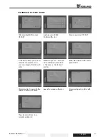
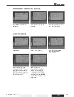
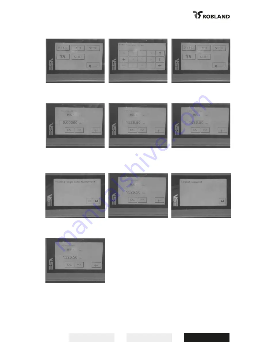
CALIBRATION OF THE GUIDE

After pressing MENU, press 
OFFSET.

In the field 0,0000 you can now 
enter the measurements of 
your saw-sample. Confirm with 
enter.

Would you like to overwrite the 
values? Confirm with enter.

The actual position is now 
correctly calibrated.

Login password 9876.
Confirm with enter.

Afterwards press 1x CAL and 
wait until the actual position 
is the same as the desired 
position. 

Leave this screen with enter.

Press once more OFFSET.

When the values are the same, 
press SAVE.

Password logout, confirm with 
enter.

Содержание NZ 3200

Страница 1: ...NZ 3200 NZ AXIS ERGO Manual Betriebsanleitung...

Страница 2: ...t of the riving knife 12 Lower sawblade cover 12 Adjusting the main sawblade and scorerblade 13 Mounting of the cross cut table 15 Mounting of the cross cut fence 15 Adjusting the cross cut fence 16 M...

Страница 3: ...English Deutsch 2 V1110 NZ3200 AXIS ERGO...

Страница 4: ...operator strictly follows the operating and safety instructions It is absolutely essential to read this manual before using the machine so you know how the machine works and what its limitations are...

Страница 5: ...stment of the machine c the correct choice of the tools for each operation d the safe handling of parts to be processed e the position of the hands in relation to the sawblade f storing the workpieces...

Страница 6: ...ohibited on the panelsaw submerged cuts by removing the riving knife and or guard all types of cuts without using the table saw fence the 90 fence or sliding table Cutting large workpieces that exceed...

Страница 7: ...ts as per ISO norm 7960 as per annexe D Workpost under load Level continuous accoustic pressure as per index A dB A Level accoustic power dB A MW Max value accoust pressure as per index C instantaneou...

Страница 8: ...0 Tilting of main saw 90 45 Max cut capacity on right side mm 1525 Saw stroke mm 3200 Option 3800 Saw arbor diameter mm 30 RPM main sawblade 3000 4000 5000 Motor power scorer KW 0 94 RPM sawblade scor...

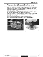
Страница 9: ...d it is still possible to move it by removing the front cover plate and placing a hand pallet truck in the two openings in the front of the frame 2 The machine must be leveled in both directions to as...

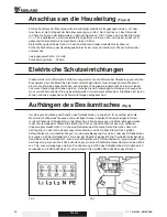
Страница 10: ...RLOADS The machine has overload protections on both saw and scoring motors Should the motor be shut off by one of these protectors it is necessary to wait a few minutes untill the overload has cooled...

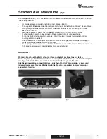
Страница 11: ...ushing the start button 6 this is only possible with the main saw motor running By pushing the stop button 5 the scorer motor is stopped when the emergency stop button 1 is pushed both motors are stop...

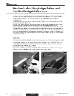
Страница 12: ...en tightened to remove the locking pin from the pulley before starting up the motor ATTENTION Only sawblade diameters from 250 to 400 mm are allowed on the machine The use of HSS sawblades is strictly...

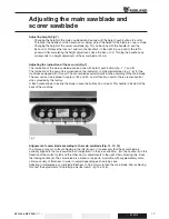
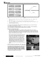
Страница 13: ...lade For slotting or grooving the riving knife has to be adjusted in such a way that the upper part of the riving knife is never set lower than the highest sawtooth in use Never remove this riving kni...

Страница 14: ...ines equipped with this part The scorer blades automatically incline according to the main blade The saw unit can be inclined in angles of 45 and 90 and at those two points there are mechanical stops...

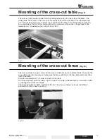
Страница 15: ...ll the button 1 in your direction and turn to the right to liberate the table Pull the sliding table till end the table will be blocked automatically when arriving in the exact position Continue this...

Страница 16: ...ube for the telescopic arm is needed option tube of 2 5 m Z482 Mounting of the cross cut fence Fig 18 The cross cut fence has got a cone and the cross cut table has got an attachment hole To position...

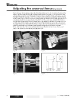
Страница 17: ...work with the telescopic extension of the guide permitting to cut at approximately 3000 mm place the knob fig 20 21 3 on the exact measurement of 2050 mm so that the scales corresponds on the two dif...

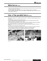
Страница 18: ...n push the handle 1 down The micrometric adjustment is achieved by locking the knob 3 by holding the handle 1 in the upright position and by turning the serrated knob 2 After the adjustment push handl...

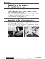
Страница 19: ...ng the sawblade while it is revolving the stop ring 2 has to be adjusted Slide the fence to about 10 mm from the sawblade Now slide the stopring 2 across the round guide bar 3 until it comes up agains...

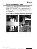
Страница 20: ...raduated scale 3 The guard can not go under the definite measurement Allowing to block the protection to avoid it goes up on its own The handle 2 as well serves as a height stop to avoid that the prot...

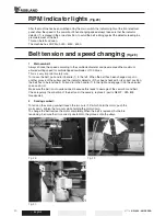
Страница 21: ...ry important safety rule To loosen the belt pull and turn handle 1 to the left When the belt has been changed or put in another groove of the pulleys and the indicator detector 2 has been checked for...

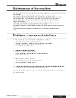
Страница 22: ...the cooling fan and motor itself In particular the sliding table needs care and attention see chapter operating the sliding table Problems causes and solutions 1 The machine does not start when the st...

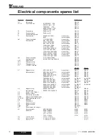
Страница 23: ...1 Magnetic relay 4KW 380V SK11 manual start N 8457 N 8467 Main sawmotor 4KW 380V SK R11CX auto star delta N 8557 N 8555 5 5KW 380V SK11 manual start N 8457 N 8467 5 5KW 380V SK R11CX auto star delta N...

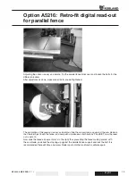
Страница 24: ...alibration of the read out is easy and simple slide the alu saw fence up against the saw blade so that the teeth just touch the fence and now push simultaneous both buttons F and SET now the read out...

Страница 25: ...der machines these 2 holes need to be drilled Now put the alu profile holding the magnetic strip onto the saw table at 1 mm below the table s front edge Make sure the sensor is put in the middle of th...

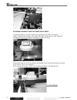
Страница 26: ...setting of the system that the active mode of the system is Abs and not Incr To change the mode of the system press the button Incr Abs Calibrating the system Place the 300 mm long piece Z1253 against...

Страница 27: ...blish its reference Be sure the table is free of all objects After the confirmation in the numerical screen you should confirm once more with the START button to be sure of the position you ve entered...

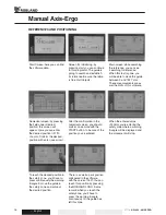
Страница 28: ...rm with enter Would you like to overwrite the values Confirm with enter The actual position is now correctly calibrated Login password 9876 Confirm with enter Afterwards press 1x CAL and wait until th...

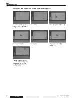
Страница 29: ...ress menu to change the direction of the aluminium profile Press save to confirm The measurement and the profiel have been adapted To change the direction of the profile once more follow the same proc...

Страница 30: ...earance you can press start and the guide will move to its position Press the flag to change the language Press Z LIJST saw list Remark when the measurement is less than 150mm you are entering the saf...

Страница 31: ...geblattes 40 Verwendung und Einstellen des Spaltkeiles 41 Schutzvorrichtung der unteren S geblatt Abdeckung 41 Einstellung des Haupts geblattes und des Vorritzers 42 Befestigung des Quertisches am Be...

Страница 32: ...English Deutsch NZ3200 AXIS ERGO V1110 31...

Страница 33: ...t auf die Vorschriften die in diesem Kapitel zusammengefasst sind Diese Maschine ist nur risikofrei zu bedienen wenn die Gebrauchsanweisungen und die Sicherheitsvorschriften genau beachtet werden Es i...

Страница 34: ...oder einer anderen Grundlage steht 3 Feinabstimmung und Installation der Maschine a F r jede Abstimmung soll die Maschine vom Netz abgekuppelt werden b Bei der Installation und der Feinabstimmung der...

Страница 35: ...reiss ge nicht vorgesehen und deshalb auch nicht erlaubt Verbotene Arbeitstechniken Folgende Arbeitsg nge sind auf der Formatkreiss ge nicht erlaubt Durchf hren von verdeckten Schnitten durch Demontag...

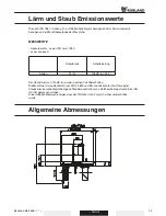
Страница 36: ...60 as per annexe D Schalldruck Schalleinstung S gen 91 A 105 dB A 26 3 Der H chstwert von 130 dB A wurde in keinen Fall berschritten Die Maschine ist staubtechnisch laut DIN 33 893 und BG Grunds tze f...

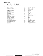
Страница 37: ...blattschwenkung 90 45 Schnittbreite mm 1525 Schnittl nge mm 3200 Option 3800 Spindeldurchmesser mm 30 Drehzahl 3000 4000 5000 Motorst rke Vorritzs ge KW 0 94 Drehzahl Vorritzs ge 8200 Durchmesser Vorr...

Страница 38: ...r Riemen Abb 1 1 Sichern Sie die Maschine gegen seitliches Verrutschen und h ngen Sie die Riemen oder Ketten so ein dass die Maschinentische keinen grossen Belastungen ausgesetzt sind Die Maschine ist...

Страница 39: ...sich ausgel st muss erst die Ursache der St rung beseitigt werden Immer darauf achten dass alle Wellen frei laufen k nnen und alle vorgesehenen Sch tzvorrichtungen aufgebaut sind Aufh ngen des Bes um...

Страница 40: ...urch dr cken des Start Knopfes 6 das ist nur m glich mit der Haupts ge Motor in betrieb Durch dr cken des Halt Knopfes 5 wird der Vorritz Motor angehalten wenn der Notstopp 1 ben tzt wird werden beide...

Страница 41: ...Beim S geblattwechsel immer darauf achten dass alle Anlagefl chen sowie Flanchen und S gebl tter sauber sind um einen stets sauberen Schnitt zu gew hrleisten Beim Vorritzs geblattwechsel den mitgelief...

Страница 42: ...s der S ge blattgrundkorper sein Der Spaltkeil ist so einzustellen dass er im Bereich der Schnitth he an jeder Stelle der gesamten Schnitth he zwischen 3 und 8 mm liegt Seine Spitze darf nicht tiefer...

Страница 43: ...r neigen sich automatisch nach dem Hauptblatt Die S ge Einheit kann in Winkeln von 45 und 90 eingestellt werden und an diese zwei Punkten gibt es ein mechanischen Halt durch die Fabrik bereitgestellt...

Страница 44: ...blockiert werden Das ist zum Beispiel sehr wichtig bei laden der Bretter oder entlang dem parallelen F hrer schneidend Das System befindet sich auf der Vorderseite des Schiebetisches Ziehen Sie den K...

Страница 45: ...teleskopischen Arm erforderlich Option R hre 2 5 M Z482 Montage des 90 Anschlages Fig 18 Der Querzaun hat einen Kegel und der Quertisch ein Befestigungsloch Um den unterst tzten F hrer auf den Querti...

Страница 46: ...d automatisch eingestellt Test die Einstellung machen Sie ein kleiner Schnitt um gerade nachzupr fen F r die Arbeit mit der teleskopischen Ausdehnung des F hrers erlaubt schneiden um etwa 3000 mm stel...

Страница 47: ...des Parallelanschlages Fig 24 Der Anschlag ist bis auf die Aluschiene komplett zusammengebaut und soll einfach auf die F hrungsstange geschoben werden Alu Anschlaglineal 5 ist stufenlos in der Tiefe e...

Страница 48: ...danach die Inbusschraube 1 wieder fest Der Anschlagring 2 soll nur soweit nach vorne auf die F hrungsstange 3 geschoben werden dass es unm glich ist mit dem Anschlaglineal das S geblatt zu ber hren N...

Страница 49: ...3 benutzend Der Schutz kann nicht unter der bestimmten Ma nahme gehen Gew hrend den Schutz zu blockieren um zu vermeiden das er selbst ndig steigt Der Griff 2 dient ebenso als ein H he Halt um zu ver...

Страница 50: ...tschalter auf Pos 0 gestellt werden ffnen Sie zuerst die Maschinent re Entspannen Sie nun der Klemmhebel 1 und drehen Sie den Hebel nach links Den Riemen in die entsprechende Scheibenstufe einlegen un...

Страница 51: ...hrt zum Garantieverlust Fehlersuche und Behebung 1 Maschine l uft nicht an nachdem die Start Taste gedr ckt worden ist Hauptschalter ein Ist der Vorwahlschalter in der richtigen Position Sind die End...

Страница 52: ...1 Leistungs Sch tz 4KW 380V SK11 manual start N 8457 N 8467 Haupts gemotor 4KW 380V SK R11CX auto star delta N 8557 N 8555 5 5KW 380V SK11 manual start N 8457 N 8467 5 5KW 380V SK R11CX auto star delt...

Страница 53: ...L cher Auf lteren Maschinen m ssen die L cher noch gebohrt werden Magnetband Halteprofiel am S getisch aufschrauben auf 1 mm unter Tischoberkante Bei der Montage darauf achten da der Sensor sich in d...

Страница 54: ...Parallelanschlag nach links bis das Aluprofiel die Z hne vom S geblatt ber hren dr cken Sie gleichzeitig die beiden Tasten F und SET jetzt steht die Ablesung auf 0 Schieben Sie jetzt den Anschlag um...

Страница 55: ...fen ob die aktive Weise des Systems Abs ist und nicht Incr Die Weise des Systems k nnen Sie ndern mittels dr cken des Knopfes Incr Abs Kalibrieren des Systems Stellen Sie das 300 Mm lange St ck Z1253...

Страница 56: ...STE drucken k nnen Sie im Programm fortfahren Der Zaun sucht und regelt seine Referenz Stellen Sie sicher dass den Tisch frei ist Nach der Best tigung auf dem numerischen Schirm m ssen Sie mit START w...

Страница 57: ...e mit ENTER M chten Sie das Ma berschreiben Best tigen Sie mit ENTER Die aktuelle Position ist jetzt richtig LOGIN Kennwort 9876 Best tigen Sie mit ENTER Drucken Sie einmal CAL und Warten Sie bis die...

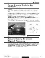
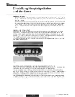
Страница 58: ...il horizontal zu setzen Drucken Sie sich SAVE um zu best tigen Das Ma und das Profil haben sich ge ndert Um die Richtung des Profils noch einmal zu ndern halten Sie das gleiche Verfahren ein Drucken S...

Страница 59: ...w nschte Position Drucken Sie die Fahne um die Sprache zu ndern Bet tigen Sie die C Liste S geliste Achtung wenn das Ma kleiner als 150mm ist erreichen Sie der Sicherheitszone In diesem Fall m ssen Si...

Страница 60: ...English Deutsch NZ3200 AXIS ERGO V1110 59...

Страница 61: ...English Deutsch 60 V1110 NZ3200 AXIS ERGO...

Страница 62: ...English Deutsch NZ3200 AXIS ERGO V1110 61...

Страница 63: ...English Deutsch 62 V1110 NZ3200 AXIS ERGO...

Страница 64: ...English Deutsch NZ3200 AXIS ERGO V1110 63...

Страница 65: ...English Deutsch 64 V1110 NZ3200 AXIS ERGO...

Страница 66: ...English Deutsch NZ3200 AXIS ERGO V1110 65...

Страница 67: ...English Deutsch 66 V1110 NZ3200 AXIS ERGO...

Страница 68: ...English Deutsch NZ3200 AXIS ERGO V1110 67...

Страница 69: ...English Deutsch 68 V1110 NZ3200 AXIS ERGO...

Страница 70: ...English Deutsch NZ3200 AXIS ERGO V1110 69...

Страница 71: ...English Deutsch 70 V1110 NZ3200 AXIS ERGO...

Страница 72: ...English Deutsch NZ3200 AXIS ERGO V1110 71...

Страница 73: ...English Deutsch 72 V1110 NZ3200 AXIS ERGO...

Страница 74: ...English Deutsch NZ3200 AXIS ERGO V1110 73...

Страница 75: ...English Deutsch 74 V1110 NZ3200 AXIS ERGO...

Страница 76: ...English Deutsch NZ3200 AXIS ERGO V1110 75...

Страница 77: ...English Deutsch 76 V1110 NZ3200 AXIS ERGO...

Страница 78: ...English Deutsch NZ3200 AXIS ERGO V1110 77...

Страница 79: ...English Deutsch 78 V1110 NZ3200 AXIS ERGO...

Страница 80: ...English Deutsch NZ3200 AXIS ERGO V1110 79...

Страница 81: ...English Deutsch 80 V1110 NZ3200 AXIS ERGO...

Страница 82: ...Printed in Belgium november 2010 Robland Kolvestraat 44 8000 Brugge Belgium Tel 32 50 458 925 Fax 32 50 458 927 www robland com...

Отзывы: