


HLA 305
9
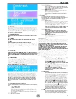
Onde Stazionarie e lo utilizza per proteggere lo stadio
di
potenza dall'eccessiva dissipazione. La condizione
ottimale è con un ROS fino a 2:1, l'amplificatore lavo-
ra al massimo guadagno. Se il valore di ROS supera il
valore di 3:1 avviene il blocco dell'amplificatore, l'avviso
sonoro dell'allarme e l'accensione fissa del simbolo di
pericolo
(
Fig.1). Per il ripristino è necessario lo
spegnimento dell'amplificatore.
In questi casi il Display indicherà nella prima riga:
Error SWR >3.0
8.4
FILTER FAULT
La scheda filtri di banda invia al microprocessore vari
segnali di stato, servono per identificare il
funzionamento regolare del filtro impostato anche in
rapporto all'efficienza dell'antenna. Se il filtro impostato
è errato, presenta un'anomalia o l'antenna è
disadattata, il processore segnala un errore, viene
emesso un segnale audio, si accende il simbolo di peri
colo
(
Fig.1) e il display indica
Err Filter.
8.5
Error Frequency
Se la frequenza rilevata dal microprocessore è fuori dal
campo di funzionamento, l'amplificatore viene bloccato,
viene emesso un segnale audio e sul display compare
la
scritta
Error Frequency
.
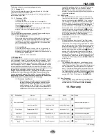
9. Garanzia
Costruzioni Elettroniche S.n.c.
Garantisce all'acquirente iniziale
un prodotto esente da difetti di fabbricazione e da difetti dei materiali
impegnati per un periodo a termine di legge dalla data di acquisto. La
riparazione dei difetti di lavorazione e la sostituzione dei componenti
difettosi verrà effettuata presso i laboratori
o i laboratori autorizzati,
sono a carico dell'acquirente solo le spese di trasporto.
L'intervento in garanzia deve essere richiesto al Distributore o Rivendi-
tore presso il quale è stato effettuato l'acquisto e che è responsabile
della garanzia. In caso che tale referente cessi la propria funzione
comunicherà al cliente un nuovo referente o accetterà a proprio insinda-
cabile giudizio se effettuare al riparazione presso la propria sede. Le
spese di spedizione da e verso il laboratorio rimarranno a carico del
cliente. Eventuali riparazioni richieste ad altri laboratori non rientreranno
English
16. Precaution
16.1
Removal from packaging and inspection
Carefully remove the amplifier from it’s packaging, and inspect for any
sign of damage incurred during shipping.
With care check each button / switch to check mechanically they oper-
ate correctly.
If any damage is found, note in as much detail as possible the problem
and immediately contact your supplier.
Retain all of the original packaging as this must be used if it is neces-
sary to return the amplifier to an approved service centre for any rea-
son.
16.2
Installation
The amplifier must be positioned in a cool and dry area that has suffi-
cient space surrounding the amplifier to allow good ventilation to all
surfaces and free flow of the surrounding air. Do not operate the amplifi-
er if it is in direct contact with sunlight. Do not place books, paper or
other objects on the top surface of the amplifier.
For details of a typical installation of the HLA305 amplifier refer to Chap-
ter 5. The PTT output from the transceiver should be connected to the
PTT input of the HLA305 (
Fig 2 ). In case there is no PTT output
from the transceiver it is still possible to use the amplifier by utilising the
internal VOX circuit . For the best control of TX/RX switching it is recom-
mend that the PTT input is utilised. The PTT input connector is an RCA/
Phono type.
Use a short length coaxial cable, type RG-58A/U,RG-8A/U or equivalent
for the connection between the output of the transceiver and the input of
the amplifier, connector RTX
Fig 2 HLA305.
Connection to the output, ANT (
Fig 2) of the HLA305 to the antenna
should not be made with low power RG-58 type cable or equivalent, but
only with a coaxial cable of sufficient power rating, for example RG-8A/
U, RG-213/U or equivalent.
The transceiver used for the input of the HLA305 must be capable of a
power output of 10-12 W to obtain the maximum output from this linear
amplifier.
16.3
Connection to DC Power Supply
The power supply for operation of the HLA305 should be capable of
13V +/- 2V DC and able to provide a current of at least 45A. Before
connecting the amplifier to the power supply (
!
Fig.2) ensure that the
voltage is correct and also that the correct polarity is observed.
If the amplifier is operated in a vehicle it must be connected directly to
the vehicles battery with a cable that has a conductor size of at least
10mm² or #7 AWG protected with a fuse at the battery of at least 40A.
16.4
ANTENNA
The HLA305 is designed for use with antennas that present a resistive
load of 50
Ω
at the frequency of operation. In the case that the antenna
does not correspond to this it will be necessary to use a system of im-
pedance matching such as an antenna tuner to provide the correct
impedance transformation. If using such a device it must be capable of
withstanding the output level of the amplifier otherwise damage to the
matching device and or the amplifier may result. The antenna must also
be tuned at low power with the amplifier switched off to avoid load mis-
match to the transistors during the tuning process.
16.5
GROUND
This amplifier
must
be connected to the RF ground system of the radio
station.
Verify that the RF ground of the station is of suitable quality, this will
eliminate noise problems on reception, prevent the build up of static
charge and avoid points of high RF voltages during transmission on
metallic objects that may come into contact with the operator. To avoid
RF interference it can be useful to use a Ferrite EMI suppressor on all
cables connected to the amplifier. (Clamp on Ferrite cores). For an
installation in a vehicle the heat sink must be electrically connected to
the chassis of the vehicle
16.6
WARNING!
Dangerous high voltages are present inside the amplifier and as such
we recommend that the cover is only removed by qualified service tech-
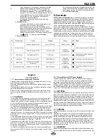
Nr
Protezione
Causa
Display
Reset
Led
Note
1
Over
Input
Power
Potenza
d’ingresso
>10W
Power
TRX
>
10W
Nessuna
azione
*
Ridurre
la
potenza
dell’ampli
fi
catore
2
3
Potenza
d’ingresso
>15W
Error
power
TRX
Spegnere
l’ampli
fi
catore
4
Over Temp
Temperatura >56°C
OVER
Temp!
Automa co
>51°C
Controllare
la
corre a
areazione
dell’ampli
fi
catore
5
Over
SWR
ROS
in
antenna
>3,0:1
Error SWR >3.0
Spegnere
l’ampli
fi
catore
Controllare
l’impianto
d’antenna
6
Filter Fault
Potenza
resa
in
antenna
insu
ffi
cente
Err Power Filt.
Spegnere
l’ampli
fi
catore
Filtro
errato
o
antenna
disada ata
7
Frequenza errata
Frequenza
<1,5
o
>30
MHz
Error Frequency
Spegnere
l’ampli
fi
catore
Controllare
la
frequenza
di
trasmis-
sione
*LED
Lampeggiante


