


IMS01N02-E4
5
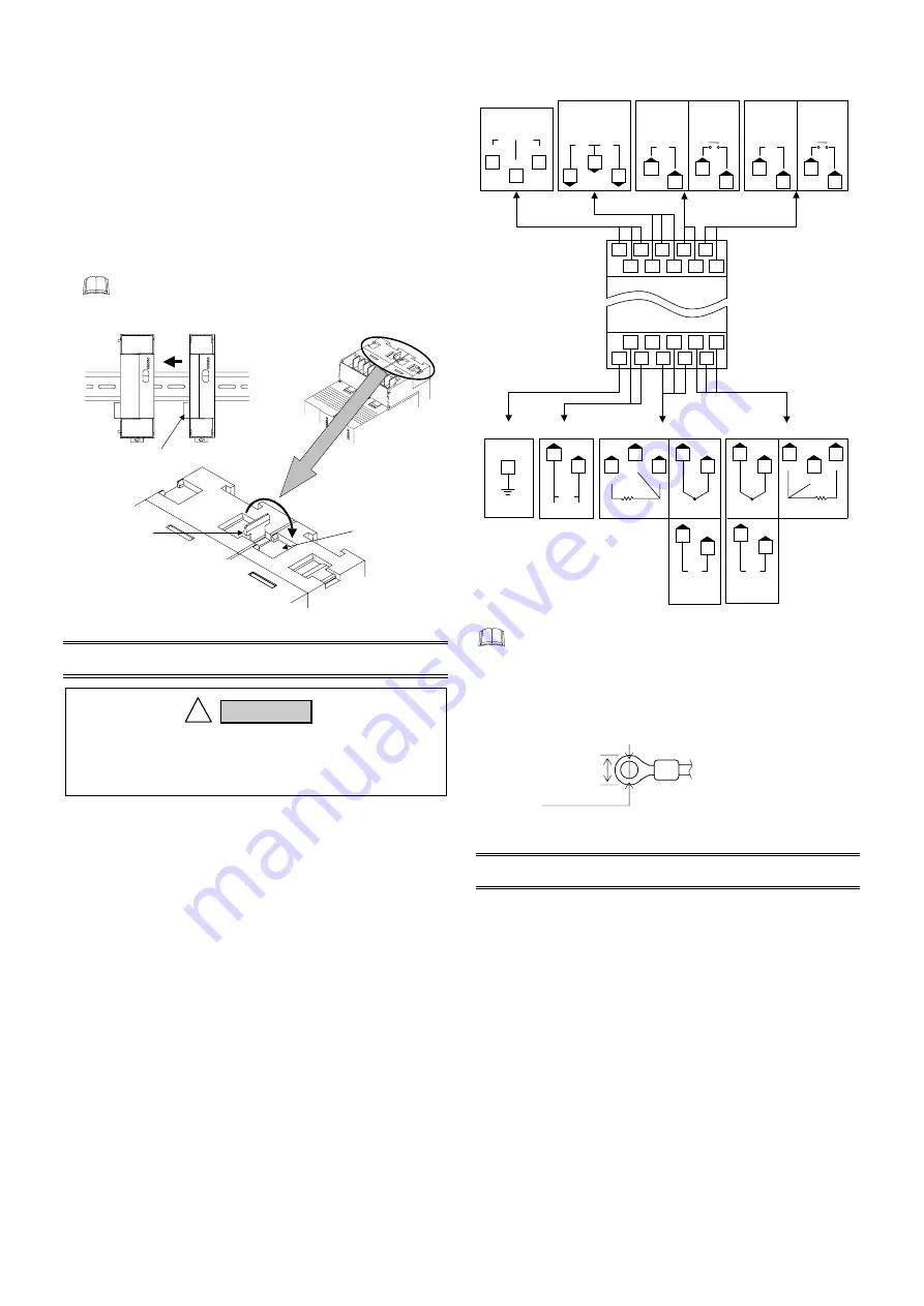
5.5 Jointing Each Module
Up to 31 SRXs consisting of the each modules can be jointed
together. Joint these modules according to the following
procedure.
Jointing procedure
1.
Mount the modules on the DIN rail and then joint these
modules together with the joint connector while sliding the
relevant module.
2.
Lift each of the joint tabs located at the top and bottom of the
module and then insert it in the slot of the adjacent module to
fix these two modules.
For panel mounting, first joint each module and then
mount it on the panel.
Joint tab
Joint connector
When viewed
from top
There is one joint tab at each
of the top and bottom of on
module. Therefore, fix two
adjacent modules with these
two joint tabs.
Joint tab
insertion slot
6. WIRING
6.1 Wiring Cautions
z
For thermocouple input, use the appropriate compensation
wire.
z
For RTD input, use low resistance lead wire with no
difference in resistance between the three lead wires.
z
To avoid noise induction, keep input signal wire away from
instrument power line, load lines and power lines of other
electric equipment.
z
If there is electrical noise in the vicinity of the instrument that
could affect operation, use a noise filter.
- Shorten the distance between the twisted power supply wire
pitches to achieve the most effective noise reduction.
- Always install the noise filter on a grounded panel.
Minimize the wiring distance between the noise filter output
and the instrument power supply terminals to achieve the
most effective noise reduction.
- Do not connect fuses or switches to the noise filter output
wiring as this will reduce the effectiveness of the noise filter.
z
Power supply wiring must be twisted and have a low voltage
drop.
z
For an instrument with 24 V power supply, supply power from
a SELV circuit.
6.2 Terminal Configuration
CT1
T/R(B)
SG
T/R(A)
RS-485
Host
communication
CT input
Control output 1
Control output 2
15
Relay contact
NO
OUT1
Voltage pulse/
Current/
Voltage
OUT1
+
−
5
2
5
2
3
6
7
16
17
+
−
24 V
DC
Power supply
Ground
Thermocouple
TC1
+
−
Input channel 1
Voltage/
Current
IN1
+
−
RTD
RTD1
B
B
A
NO
OUT2
OUT2
+
−
4
1
4
1
10
13
10
14
13
13
10
TC2
+
−
IN2
+
−
9
12
8
12
12
9
RTD2
B
B
A
9
Input channel 2
19
18
20
FG
16 15
3
2
1
17
7
6
5
4
20 19 14 13 12
18 11 10 9
8
Upper-side terminal
CT2
Relay contact
Voltage pulse/
Current/
Voltage
Lower-side terminal
Thermocouple
RTD
Voltage/
Current
Voltage/
Current
•
Terminal No. 11 is not used.
•
Input channel 2 can be used as remote setting input
(only for voltage/current input).
In this case, control output 2 and CT input 2 become
unused.
•
Use the solderless terminal appropriate to the screw
size (M3)
.
7. SPECIFICATIONS
Inputs
Number of inputs:
2 points (Isolated between each channel)
Input type:
•
Thermocouple
K, J, T, S, R, E, B, N (JIS-C1602-1995)
PLII
(NBS)
W5Re/W26Re
(ASTM-E988-96)
•
RTD:
Pt100 (JIS-C1604-1997)
JPt100 (JIS-C1604-1989, Pt100 of
JIS-C1604-1981)
•
Voltage (low):
0 to 10 mV, 0 to 100 mV, 0 to 1 V
•
Voltage (high):
0 to 5 V, 0 to 10 V, 1 to 5 V
•
Current:
0 to 20 mA, 4 to 20 mA
(Input impedance: 250
Ω
)
Sampling cycle:
25 ms
PV bias:
−
Input span to
+
Input span
CT input:
2 points
0.0 to 30.0 A (CTL-6P-N) or
0.0 to 100.0 A (CTL-12-S56-10L-N)
To prevent electric shock or instrument failure, do
not turn on the power until all the wiring is
completed.
!
WARNING
5.9 mm or less
3.2 mm or more
Recommended tightening
torque:
0.4 N
⋅
m (4 kgf
⋅
cm)


