RIX
Industries
MAN
‐
2V3B
‐
4.1V
‐
P1
Page
17
c.
Remove the valve seat from the cylinder head. Remove o-rings, suction reed
valve and discharge reed valves. Discard all o-rings. Care must be taken not
to damage valve seat.
d
Inspect and repair or replace parts as necessary. All o-rings must be replaced.
VALVE
INSTALLATION
a.
Attach the two discharge reeds on the discharge (upper) side of valve seat and
the suction reed on the suction (lower) side of seat and tighten securely.
Inspect to see that the valves rest flush against the seat.
b.
Install O-ring on top of cylinder.
c.
Place valve assembly on cylinder, making sure that the valve seat is positioned
so that the spring pin enters the hole in the valve seat.
d. Install head on valve assembly with 1.025" diameter counter-bore for
discharge port towards the flywheel side of pump.
e.
Bolt down assembly with nuts and flat washers and torque to 30 ft-lbs.
7.4.3
3RD
STAGE
VALVE
ASSEMBLY
VALVE
REMOVAL
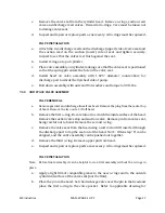
a.
Remove gas inlet and discharge lines from head. Remove the plug from the center top
of head. Remove the two nuts. Lift off head.
b.
Remove the first o-ring. Be careful not to scratch the inside surface of the head.
Remove the suction valve stop and suction valve. Remove pin from valve seat,
being careful not to bend. Remove the second o-ring.
c.
Remove the valve seat from the head using a soft rod or drift inserted through
the discharge port to tap the seat out of the head. N
OTE
: Often step "b" can be
skipped, and the entire assembly can be pushed out together.
d.
Remove the third o-ring. Remove upper pin from head.
e.
Inspect and repair or replace parts as necessary. All o-rings must be replaced.
VALVE
INSTALLATION
Note: Before final assembly it can be helpful to do a trial assembly without the o-rings in
place.
a.
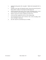
Apply a light film of compatible grease to the new o-rings and to the outside
cylindrical surface of the valve seat (not the flats).
b.
Place the pin in the head. Set the discharge valve over the pin in the head and
place the first o-ring in the valve pocket. Refer to applicable drawing for
Содержание 2V3B-4.1V-P1A
Страница 46: ...RIX Industries MAN 2V3B 4 1V P1 Page 37 FIGURE 1 GENERAL COMPRESSOR DETAIL 1 4 ...
Страница 47: ...RIX Industries MAN 2V3B 4 1V P1 Page 38 FIGURE 2 GENERAL COMPRESSOR DETAIL 2 4 ...
Страница 48: ...RIX Industries MAN 2V3B 4 1V P1 Page 39 FIGURE 3 GENERAL COMPRESSOR DETAIL 3 4 ...
Страница 49: ...RIX Industries MAN 2V3B 4 1V P1 Page 40 FIGURE 4 COMPRESSION VALVE DETAIL ...
Страница 50: ...RIX Industries MAN 2V3B 4 1V P1 Page 41 FIGURE 5 GENERAL COMPRESSOR DETAIL 4 4 ...
Страница 51: ...RIX Industries MAN 2V3B 4 1V P1 Page 42 FIGURE 6 FIRST STAGE COMPRESSION STAGE DETAIL ...
Страница 52: ...RIX Industries MAN 2V3B 4 1V P1 Page 43 FIGURE 7 SECOND AND THIRD STAGE COMPRESSION STAGE DETAIL ...
Страница 53: ...RIX Industries MAN 2V3B 4 1V P1 Page 44 FIGURE 8 SUCTION AND FIRST STAGE PLUMBING DETAIL ...
Страница 54: ...RIX Industries MAN 2V3B 4 1V P1 Page 45 FIGURE 9 SECOND AND THIRD STAGE PLUMBING DETAIL ...
Страница 55: ...RIX Industries MAN 2V3B 4 1V P1 Page 46 FIGURE 10 FINAL DISCHARGE PLUMBING DETAIL ...
Страница 56: ...RIX Industries MAN 2V3B 4 1V P1 Page 47 FIGURE 11 CRANKCASE ASSEMBLY DETAIL ...
Страница 57: ...RIX Industries MAN 2V3B 4 1V P1 Page 48 FIGURE 12 CONNECTING ROD DETAIL ...
Страница 58: ...RIX Industries MAN 2V3B 4 1V P1 Page 49 FIGURE 13 CONTROL BOX ASSEMBLY DETAIL 1 3 ...
Страница 59: ...RIX Industries MAN 2V3B 4 1V P1 Page 50 FIGURE 14 CONTROL BOX ASSEMBLY DETAIL 2 3 ...
Страница 60: ...RIX Industries MAN 2V3B 4 1V P1 Page 51 FIGURE 15 CONTROL BOX ASSEMBLY DETAIL 3 3 ...
Страница 61: ...RIX Industries MAN 2V3B 4 1V P1 Page 52 FIGURE 16 WIRING SCHEMATIC ...
Страница 62: ...RIX Industries MAN 2V3B 4 1V P1 Page 53 FIGURE 17 ELECTRICAL SCHEMATIC ...
Страница 65: ...RIX Industries MAN 2V3B 4 1V P1 Page 55 FIGURE 18 FLOW SCHEMATIC ...
Страница 70: ...RIX P N 76 713 X76 713 DWG A8042 CUI SP CTI PROPIN ...
Страница 71: ...RIX P N 76 713 X76 713 DWG A8042 CUI SP CTI PROPIN ...
Страница 77: ......
Страница 78: ......
Страница 79: ......
Страница 80: ......
Страница 81: ... ǣ ...
Страница 82: ... Ǥ ǣ ...

