


RIX
Industries
MAN
‐
2V3B
‐
4.1V
‐
P1
Page
2
CHAPTER
2:
INSTALLATION
2.1
MOUNTING
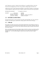
The compressor must be firmly bolted down to a rigid foundation through all mounting holes to
minimize vibration. Any allowed movement will generally increase vibration which can lead to
component damage.
Due to the inherent danger of fire and/or explosion during O2 compression, flammable substances
should not be stored near the unit and the frequency of personnel coming in close contact with the
compressor during operation should be minimized. RIX recommends keeping a supply of high
purity N2 for start-up and testing of the compressor—see the O2 burn-in procedure in
Section
3.2
.
2.2
GAS
PLUMBING
Be sure all process lines are free from contamination. Plumbing to the compressor must be sized so
that pressure at the compressor suction is within the range given in
Compressor
Specifications
.
Discharge plumbing must be large enough to pass design flow at lowest expected back pressure
without choking the flow. User’s suction and discharge plumbing should be designed to
accommodate compressor vibration.
CAUTION
If flexible lines are used, user is responsible to secure those lines
to prevent whipping in case of breakage.
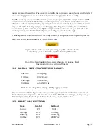
Safety relief valves are installed on the compressor at each stage of compression: suction,
interstage, and discharge. Do not start the compressor without these items properly installed. All
plumbing and components must be rated for pressures greater than the connected relief valve
setting.
Provisions must be in place to relieve all internal pressure and isolate the compressor from all
external pressure sources to ensure that the unit can be safely disassembled for maintenance. It
may be helpful to install a hand valve in the gas line downstream of the compressor to create back
pressure for testing and calibration.
DANGER
Do not install ball valves in either suction or discharge plumbing. If
closed quickly, these valves can cause fire and/or explosion.
2.3
CRANKCASE
LUBRICATION
Check the crankcase oil level via sight glass (oil level should be ¾ way up the sight glass) and
inspect for contamination from water or other foreign material. To add oil unscrew the plastic vent
Содержание 2V3B-4.1V-P1A
Страница 46: ...RIX Industries MAN 2V3B 4 1V P1 Page 37 FIGURE 1 GENERAL COMPRESSOR DETAIL 1 4 ...
Страница 47: ...RIX Industries MAN 2V3B 4 1V P1 Page 38 FIGURE 2 GENERAL COMPRESSOR DETAIL 2 4 ...
Страница 48: ...RIX Industries MAN 2V3B 4 1V P1 Page 39 FIGURE 3 GENERAL COMPRESSOR DETAIL 3 4 ...
Страница 49: ...RIX Industries MAN 2V3B 4 1V P1 Page 40 FIGURE 4 COMPRESSION VALVE DETAIL ...
Страница 50: ...RIX Industries MAN 2V3B 4 1V P1 Page 41 FIGURE 5 GENERAL COMPRESSOR DETAIL 4 4 ...
Страница 51: ...RIX Industries MAN 2V3B 4 1V P1 Page 42 FIGURE 6 FIRST STAGE COMPRESSION STAGE DETAIL ...
Страница 52: ...RIX Industries MAN 2V3B 4 1V P1 Page 43 FIGURE 7 SECOND AND THIRD STAGE COMPRESSION STAGE DETAIL ...
Страница 53: ...RIX Industries MAN 2V3B 4 1V P1 Page 44 FIGURE 8 SUCTION AND FIRST STAGE PLUMBING DETAIL ...
Страница 54: ...RIX Industries MAN 2V3B 4 1V P1 Page 45 FIGURE 9 SECOND AND THIRD STAGE PLUMBING DETAIL ...
Страница 55: ...RIX Industries MAN 2V3B 4 1V P1 Page 46 FIGURE 10 FINAL DISCHARGE PLUMBING DETAIL ...
Страница 56: ...RIX Industries MAN 2V3B 4 1V P1 Page 47 FIGURE 11 CRANKCASE ASSEMBLY DETAIL ...
Страница 57: ...RIX Industries MAN 2V3B 4 1V P1 Page 48 FIGURE 12 CONNECTING ROD DETAIL ...
Страница 58: ...RIX Industries MAN 2V3B 4 1V P1 Page 49 FIGURE 13 CONTROL BOX ASSEMBLY DETAIL 1 3 ...
Страница 59: ...RIX Industries MAN 2V3B 4 1V P1 Page 50 FIGURE 14 CONTROL BOX ASSEMBLY DETAIL 2 3 ...
Страница 60: ...RIX Industries MAN 2V3B 4 1V P1 Page 51 FIGURE 15 CONTROL BOX ASSEMBLY DETAIL 3 3 ...
Страница 61: ...RIX Industries MAN 2V3B 4 1V P1 Page 52 FIGURE 16 WIRING SCHEMATIC ...
Страница 62: ...RIX Industries MAN 2V3B 4 1V P1 Page 53 FIGURE 17 ELECTRICAL SCHEMATIC ...
Страница 65: ...RIX Industries MAN 2V3B 4 1V P1 Page 55 FIGURE 18 FLOW SCHEMATIC ...
Страница 70: ...RIX P N 76 713 X76 713 DWG A8042 CUI SP CTI PROPIN ...
Страница 71: ...RIX P N 76 713 X76 713 DWG A8042 CUI SP CTI PROPIN ...
Страница 77: ......
Страница 78: ......
Страница 79: ......
Страница 80: ......
Страница 81: ... ǣ ...
Страница 82: ... Ǥ ǣ ...