background image

4

Ri4Power System 185 mm Montageanleitung/Ri4Power system 185 mm assembly instructions/Ri4Power système 185 mm – Notice de montage

++++

++

++

++

++

max

.

max

.

____

____

A

++++

++

++

++

++

max

.

max

.

____

____

A

2. Hinweise zur Dokumentation

2. Notes on documentation

2. Remarques relatives à la documentation

3. Sicherheitshinweise

3. Safety notes

3. Consignes de sécurité 

Die 

Montageanleitung

 richtet sich an alle 

Personen, die über eine entsprechende 

Fachausbildung verfügen, um Schaltschränke 

normgerecht mit elektrischen, elektronischen, 

mechanischen und pneumatischen Betriebs-

mitteln auszurüsten bzw. zu montieren und 

betriebsfertig anzuschließen.

CE-Kennzeichnung

Die Konformitätserklärung steht als Download 

auf der Homepage von Rittal zur Verfügung.

The 

assembly instructions

 are aimed at 

personnel who have completed correspond-

ing technical training and are thus qualified to 

set up enclosures with electrical, electronic, 

mechanical and pneumatic equipment in 

accordance with applicable standards and to 

erect, assemble and connect such enclosures 

at the place of use.

CE labelling

The declaration of conformity is provided for 

download on the Rittal website.

La 

notice de montage

 s'adresse à toutes 

les personnes qui possèdent la formation 

technique suffisante pour le montage, l'instal-

lation sur site et le raccordement d'armoires 

électriques selon les normes électriques, 

électroniques, mécaniques et pneumatiques 

en vigueur.

Certification CE

La déclaration de conformité peut être  

téléchargée depuis le site Internet de Rittal.

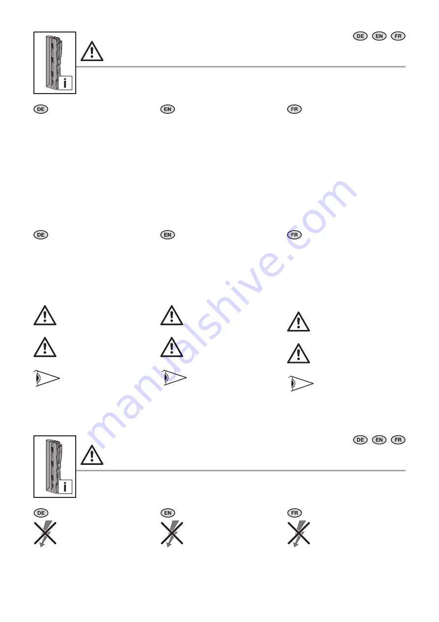
Verwendete Symbole

Beachten Sie folgende Sicherheits- und sons-

tige Hinweise in der Anleitung:

Symbol für eine Handlungsanweisung:


◾ Der Blickfangpunkt zeigt an, dass Sie eine 

Handlung durchführen sollen.

Sicherheits- und andere Hinweise:

Gefahr! 

Unmittelbare Gefahr für Leib 

und Leben.

Achtung! 

Mögliche Gefahr für Produkt 

und Umwelt.

Beachten!

Symbols used

Observe the following safety and other notes 

in the instructions:

Symbol identifying required actions:


◾ The bullet point indicates an action to be 

performed.

Safety and other notes:

Danger! 

Immediate danger to life and 

limb.

Caution! 

Potential threat to the product 

and its environment.

Note! 

Symboles utilisés

Tenir compte des consignes de sécurité et 

autres directives contenues dans cette notice :

Symbole indiquant une action à effectuer :


◾ Le pictogramme en caractère gras indique 

que vous devez exécuter une action.

Consignes de sécurité et  

autres directives :

Danger ! 

Risque de blessure grave, voire 

mortelle.

Attention ! 

Danger éventuel pour le produit 

et l'environnement.

Attention !


Vor Installation- oder Service-

arbeiten Stromversorgung 

unterbrechen, um Unfälle zu 

vermeiden. Die Geräte müssen 

in einem passenden Gehäuse 

eingebaut und gegen Ver-

schmutzung geschützt werden. 

Inbetriebsetzung und Wartung 

nur durch Fachpersonal!


To prevent electric shock, 

disconnect from power source 

before installing or servicing. 

Install in suitable enclosure. 

Keep free from contaminants. 

To be commissioned and 

maintained only by qualified 

personnel!


Avant le montage et la mise en 

service, couper l'alimentation 

secteur afin d'éviter tout 

accident. Prevoir une mise en 

coffret ou armoire appropriée, 

protéger le produit contre les 

environnements agressifs. Mise 

en service et entretien : 

seulement par du personnel 

spécialisé !

Содержание SV 9677.000

Страница 1: ...ung Assembly instructions Notice de montage NH Sicherungs Lastschaltleisten Gr 00 NH slimline fuse switch disconnectors size 00 Coupe circuits à fusibles HPC taille 00 SV 9677 000 SV 9677 010 SV 9677 015 SV 9677 025 ...

Страница 2: ...e 11 8 Connections 11 9 Top connections 13 10 Always use cover for top connections 14 11 Inserting the fuse 15 12 Locking the fuse holder 15 13 Sealing 16 14 Voltage test 16 15 Accesories Current converter assembly and cable routing 16 16 Accesories Pilot switch assembly 17 17 Accesories Pilot switch cable routing 18 18 Electronic fuse monitoring 18 1 Caractéristiques techniques 2 2 Remarques rela...

Страница 3: ... pole 3 pôles 3 polig 3 pole 3 pôles 3 polig 3 pole 3 pôles Leitungsabgang Cable outlet Départ de ligne oben unten Top bottom En haut en bas oben unten Top bottom En haut en bas oben unten Top bottom En haut en bas Anschlussart Type of connection Type de raccordement Schraube M8 Screw M8 Vis M8 Schraube M8 Screw M8 Vis M8 Rahmenklemme Box terminal Bride à étrier Anschluss von Rundleitern mm Connec...

Страница 4: ...en Sie folgende Sicherheits und sons tige Hinweise in der Anleitung Symbol für eine Handlungsanweisung Der Blickfangpunkt zeigt an dass Sie eine Handlung durchführen sollen Sicherheits und andere Hinweise Gefahr Unmittelbare Gefahr für Leib und Leben Achtung Mögliche Gefahr für Produkt und Umwelt Beachten Symbols used Observe the following safety and other notes in the instructions Symbol identify...

Страница 5: ... personeel Ska installeras av behörig elektriker L installazione deve essere eseguita da un elettricista qualificato Instalación a reali zar por un técnico electricista cualificado max max ________A Turvallisuusohjeet Sikkerhedsanvisninger Wskazówki dotyczące bezpieczeństwa Bezpečnostní pokyny Инструкции за безопасност Меры безопасности Υποδείξεις ασφαλείας Varoitus liikkuvista mekaanisista osista...

Страница 6: ...šme tiem Opozorilo pred ostrim predme tom A se citi manualul Pročitajte upute Az utasítást el kell olvasni Skaityti instrukciją Lugeda kasutus juhendit Izlasiet instrukciju Preberite navodila Instalarea se va face de un electrician calificat Instalaciju smije provesti samo ovlašteno stručno osoblje za elektri čarske radove A szerelést elektromos szak embernek kell elvégeznie Turi įrengti elek trik...

Страница 7: ...ems 4 Jeux de barres 5 Montage Schraubbefestigung 185 mm Wöhner 5 Screw attachment 185 mm Wöhner 5 Fixation par vis 185 mm Wöhner A 50 max max _____ ___A 185 185 150 10 50 650 25 max max _____ ___A 1 max max 3 2 2 max max 4 4 50 M8 8 8 12 Nm 110 lb in 5 1 5 2 4 1 A mm 30 40 60 80 100 120 DIN 6796 0 8x4 SW13 mm mm 4 2 185 mm Rückbereich Mitte Rear section 185 mm centre Partie arrière au milieu 185 ...

Страница 8: ...m 185 mm assembly instructions Ri4Power système 185 mm Notice de montage 3 2 51 7 nur only IP20 3x 4 5 6 Montage Klemmbefestigung 185 mm Wöhner 6 Clamping attachment 185 mm Wöhner 6 Fixation par borne 185 mm Wöhner 3 1 2 43 2 IP20 6 1 6 3 6 2 9677 450 PZ2 mm ...

Страница 9: ...tructions Ri4Power système 185 mm Notice de montage 6 Montage Klemmbefestigung 185 mm Wöhner 6 Clamping attachment 185 mm Wöhner 6 Fixation par borne 185 mm Wöhner 3 2 1 6 4 ____ ____ A max max max max 4 10 185 185 2 2 3 ____ ____A max max 1 4 8 Nm 70 lb in 6 5 PZ2 0 8x4 IS4 mm ...

Страница 10: ...A ____ ____ A max max max 1 1 2 2 ____ ____ A ____ ____ A max max max 3 x 3 x 6 6 0 8x4 IS4 7 Montage Schraubbefestigung Rückbereich 185 mm Mitte 7 Screw attachment rear section 185 mm centre 7 Fixation par vis en partie arrière au milieu 185 mm mm Montageanleitung A 5 Die Form 2b Assembly instructions A5 The Form 2b Notice de montage A5 La forme 2b DE EN FR 7 1 9686 800 3 x 2x50 9684 0xx 6 x 185 ...

Страница 11: ...x Kabelschuh max Cable lugs cosse de câble max DIN 46 234 70 mm2 DIN 46 235 70 mm2 95 mm2 8 1 8 2 7 Montage Schraubbefestigung Rückbereich 185 mm Mitte 7 Screw attachment rear section 185 mm centre 7 Fixation par vis en partie arrière au milieu 185 mm max max _____ ___A 1 max max 3 2 2 7 2 7 3 SW13 SW13 A Ø8 4 DIN 6796 Anzahl Qty Quantité 9684 0xx A M8 8 8 ISO 4017 L mm 2x50 35 4x50 55 3x 12 Nm 18...

Страница 12: ...ge Dismantling Démontage 20 12 M6 5 5 Nm 48 lb in re 1 5 10 mm rm 1 5 95 mm f AE 1 5 70 mm 95 mm je nach Verpressung der AE 95 mm depending on how cable lugs are crimped 95 mm en fonction de la manière dont les cosses de câbles sont fixés 1 5 70 mm M5 3 5 Nm 31 lb in 70 95 mm 70 mm rm sm f f AE 95 mm rm sm f 10 50 mm rm sm f f AE 9677 420 clic 1 2 9677 400 8 3 8 4 8 6 8 5 mm 1x6 IS4 mm ...

Страница 13: ...i4Power system 185 mm assembly instructions Ri4Power système 185 mm Notice de montage 9 Anschlüsse oben 9 Top connections 9 Raccordements par le haut max max ____ ____ A max max ____ ____ A max max 1 2 2 3 max max max max 1 180 2 3 3 9 1 9 2 PZ2 ...

Страница 14: ...me 185 mm Notice de montage 9 Anschlüsse oben 9 Top connections 9 Raccordements par le haut 10 Abdeckung bei Anschlüssen oben immer verwenden 10 Always use cover for top connections 10 Toujours utiliser le recouvrement lors des raccordements par le haut clic 2 1 180 2 1 4 3 5 5 9677 405 3x 9 3 10 1 PZ2 ...

Страница 15: ... Ri4Power système 185 mm Notice de montage 11 Sicherung einsetzen 11 Inserting the fuse 11 Introduction du fusible 12 Abschließbarkeit 12 Locking the fuse holder 12 Cadenassage max max ____ ____ A max max ____ ____ A clic 2 1 1 2 1 3 max max ____ ____ A max max ________A 3x 11 1 12 1 12 2 ...

Страница 16: ...ing 13 Plombage 15 Zubehör Stromwandler Einbau und Kabelverlegung 15 Accesories Current converter assembly and cable routing 15 Accessoires transformateur montage et guidage des câbles 14 Spannungsprüfung 14 Voltage test 14 Test de tension max max ____ ____ A max max ____ ____ A max max ________A max max ________A 2 3 1 9677 810 3x 13 1 14 1 15 1 PZ2 ...

Страница 17: ...er Einbau und Kabelverlegung 15 Accesories Current converter assembly and cable routing 15 Accessoires transformateur montage et guidage des câbles 16 Zubehör Meldeschalter Einbau 16 Accesories Pilot switch assembly 16 Accessoires montage des micro commutateurs max max ________A max max ________A max max clic 3071 000 15 2 16 1 DIN 46244 2 8 x 0 5 mm ...

Страница 18: ...mutateurs guidage des câbles 18 Elektronische Sicherungsüberwachung 18 Electronic fuse monitoring 18 Surveillance des fusibles électroniques max max ________A Innen inside à l intérieur Außen outside à l extérieur 17 1 18 1 14 2 17 2 LED L1 L2 L3 11 14 11 14 Reset Reset or LED 12 L1 L2 L3 Q1 11 21 14 22 24 X1 BR X2 X1 X2 With bridge BR Non latching High LED red Low LED green Without bridge BR Latc...

Страница 19: ...chnis List of model numbers Liste des références Best Nr Model No Référence Kapitel Chapter Chapitre 3071 000 16 9677 000 5 6 7 9677 010 5 6 7 9677 015 5 6 7 9677 025 5 6 7 9677 400 8 9677 405 10 9677 420 8 9677 450 6 9677 810 15 9684 004 5 6 7 9684 006 5 6 7 9684 008 5 6 7 9684 010 5 6 7 9684 012 5 6 7 9686 800 7 9686 820 7 max max ________A ...

Страница 20: ...oftware Services www rittal com contact You can find the contact details of all Rittal companies throughout the world here RITTAL GmbH Co KG Auf dem Stuetzelberg 35745 Herborn Germany Phone 49 2772 505 0 E mail info rittal de www rittal com 03 2021 D 0000 00000674 03 ...

Отзывы: