Siemens CPD6, Information And Instruction Manual
The Siemens CPD6 is an advanced device known for its exceptional performance and reliability. To make the most of its features, it's essential to have the comprehensive Information and Instruction Manual. Download the free manual from manualshive.com, ensuring you have access to all necessary details to maximize your CPD6 experience.
Share
Download


Reviews:
No comments
Related manuals for CPD6

PFR-5
Brand: Eaton Pages: 4

ETR4-70-A
Brand: Eaton Pages: 3

AEGIS AG II IT DN0 Series
Brand: Eaton Pages: 2

HFC21B
Brand: NATIONAL SWITCHGEAR Pages: 24

B20B-VR Series
Brand: Eaton Pages: 42

1653B
Brand: Fluke Pages: 5

POWELL PowlVac-ND 4 Series
Brand: Safety Pages: 74

RCBO 16-30 Mini
Brand: Votronic Pages: 2

F-11
Brand: Westinghouse Pages: 20

ISM_LD Series
Brand: TAVRIDA ELECTRIC Pages: 70

EntelliGuard GT-H
Brand: GE Pages: 62

AM-13.8-500-7
Brand: GE Pages: 32

AM-4.16-250-6
Brand: GE Pages: 32
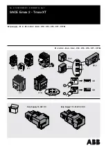
SACE Emax 2
Brand: ABB Pages: 10


