NATIONAL SWITCHGEAR HFC21B, Instructions Manual
Looking for the manual for your National Switchgear HFC21B? Look no further! You can easily download the free instructions manual from manualshive.com, allowing you to effortlessly navigate and maximize the potential of your National Switchgear HFC21B. Get your manual now and take full control of your product's capabilities.
Share
Download


Reviews:
No comments
Related manuals for HFC21B

PKZ Series
Brand: Eaton Pages: 3

PKZM0 PI Series
Brand: Eaton Pages: 2

T0 I2-NA Series
Brand: Eaton Pages: 4

Power Defense PD5
Brand: Eaton Pages: 8

XMX-NET-PD-A
Brand: Eaton Pages: 4

UL1066 Magnum
Brand: Eaton Pages: 4

RASP5 EIP Series
Brand: Eaton Pages: 16

RVU Series
Brand: Eaton Pages: 16

ZP-IHK
Brand: Eaton Pages: 2

BA88-31
Brand: IEK Pages: 14

F-ARI Test Series
Brand: ABB Pages: 18

DA-075-DJ25
Brand: SALTEK Pages: 2

3VT9100-4TN30
Brand: Siemens Pages: 4

3VT9100-8CE00
Brand: Siemens Pages: 4

GL 311 F3/4031 P/VE
Brand: GE Pages: 146

Handheld Inductive Loop Tester HILT 9000
Brand: ATSI Pages: 17
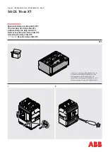
SACE Tmax XT
Brand: ABB Pages: 6

3VF7
Brand: Siemens Pages: 12


