4
Publication:
AMEN00395 2020-07-06
4
PUB. NO. FLSFLDG SEPTEMBER 2015
NOTE: The FLASHFOLD can be installed as a free standing
unit or mounted to a wall or a machine structure in a
machining, welding type of environment:
1.
Which workstation will I be working at and which side of
the workstation is the unit to be located?
2.
Check that floor is in sound condition, does not have
cracks or flaws and is there anything buried in the floor
where the anchors go?
3.
Does the installation allow for clearance for robotic,
machining, welding or other types of operation?
4.
Does the installation meet all applicable robotic,
machining, welding or other workstation safety
requirements such as is contained in the following:
a. OSHA Instruction CPL 2-1.24 (Mechanical Power Presses)
b. UL Standard for Safety UL 325 (Door, Drapery, Gate,
Louver and Window Operators and Systems)
c. ANSI RIA R 15.06-1986 (Industrial Robots and Robot
Systems-Safety Requirements)
5.
Are any special work permits required?
6.
Are there any overhead obstructions?
7.
Is a qualified electrician ready to bring in the power and
wire up the controls?
8.
Can electrical power to the workstation be shut off without
interfering with other plant operations?
9.
Can material handling equipment (forklifts) be detoured
during installation.
10. How will the work area be barricaded?
11.
Does the customer wish to be present to observe?
12. Check floor across the width using a long level.
NOTE: The floor must be level so that the header and
curtain container will be level and the header
guides will be plumb.
13. Based on the floor or wall mounting brackets provided,
anchor as follows.
Concrete Floor:
Anchors, minimum 3/8” x 2 3/4” [10x70] long.
2”x4” [51x102] Wood Wall Minimum :
3/8” x 1 1/2” [10x38]
Lag screws.
Steel Wall 7ga Minimum:
Weld, 3/8” [10] Tap/Drill, 1/2” [13] Thru Bolt or 1/4”-14 [6]
Self Tap/Drill
FLASHFOLD
™
MODEL FLSFLD
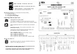
CHAPTER 2 - INSTALLATION INSTRUCTIONS
Crate Containing the following
1
Header
2/4
Container Covers
1
Curtain Container
a/r
Curtain Container Floor
2
Header Guides
1
Curtain
1
Motor/Brake/Gearbox Assembly w/13’ of cable
1
Motor Mount
1
Drive Shaft Assembly
1
Drive Shroud
1
Control Box w/ Owner’s Manual (optional)
4
Curtain Guides (optional)
1
Reversing Edge (optional)
1
Reversing Edge Chain (optional)
1
Reversing Edge Cable (optional)
1
Interrupt Switch Assembly (optional)
1
Photoeye Assembly (optional)
2/4
Long Side Mounting Brackets (optional)
Parts Box Containing the Following
1
Owners Manual
1
Non-Drive Guide Cap
4
Short Side Mounting Brackets (only if long are
not chosen)
1
Belt Idle (long)
1
Drive Belt (short w/2 loops)
2
Idle Belt Attachment Brackets
2
Idle Belt Attachment Plates
1
Limit Switch Sprocket Large w/Set Screws (2)
1
Chain (#35) Limit Switch (15 3/4”)
1
Limit Switch Chain Link (#35)
1
3/16” x 1/4” x 4 1/2” Key
1
Retaining Ring
4
M8 x 1.25 x 25mm Bolts
4
3/8-16 X 3/4” Bolts
4
3/8” Lock Washers
8
1/4” Lock Washers
20
1/4-20 x 3/4” Hex Head Bolts
20
1/4” “T” Nuts
30
#12-14 x 3/4” Self Tap/Drill Screws
QUANTITY
DESCRIPTION
PARTS PACKAGES