background image

Rinnai New Zealand

Compact Op/Install Manual: 10170-C 02-09

9

Customer Information - Troubleshooting

Symptom

Cause

Solution

Burner will not light No power present

No gas present
Power cut
Air in gas pipe
Ignition failure

Ensure power cord is plugged in and turned on
Ensure gas supply is turned on
Re-ignite after power is restored
Installer to do - purge air
Repeat ignition steps

Smell of gas

Leaking gas

Turn off gas at meter or LPG cylinder and call installer

Fan not working

Heat switch is not activated
No power present

Allow heater to run on HIGH for approximately 5 mins
Ensure power cord is plugged in and turned on

Small soot deposit

Normal operation

No action required

Severe soot 

deposits forming 

on logs or glass

Inadequate flue system, incorrect 

gas pressure or log misalignment

Call a Rinnai Service Centre

Condensation on 

glass

Normal operation

Allow heater to warm-up and condensation will 

disappear

Streaky lines on 

glass

Normal operation

Clean glass

During installation there will be an initial burning in period where some smoke and smell may 

be experienced. This is a normal part of the operation.

The appliance is fitted with an overheat safety switch. Under overheating conditions this switch 

will shut off the appliance. If the appliance shuts off repeatedly servicing may be required.

Abnormal flame pattern

Each Rinnai Flame Fire has a distinct flame pattern. This should look the same every time you 

start your fire, after an initial warm up period of approximately 20 minutes.

Abnormal flame performance and/or pattern can indicate a problem with your fire, such as 

blocked gas injectors or artificial logs/burn media have shifted from when the fire was first 

installed. There are some warning signs that could indicate a problem.

Unusual smell from the appliance

Continued difficulty or delay in establishing a flame

Flame appears either very short or very long 


Flame only burns part way across the burner

Severe soot building up on the inside of the glass door

If any of the above signs occur, please call Rinnai to discuss.

Normal

Abnormal

Содержание 0901 7042

Страница 1: ...r combustible opening installations a Rinnai Zero Clearance Box and Flue Kit is mandatory To be installed or operated in places where painting is taking place or in places such as hair salons where there is a lot of dust and fluff and where aerosols are used Appliance must only be installed with an approved Rinnai flue system Appliance must be installed commissioned and serviced by a licensed trad...

Страница 2: ... only This warranty will not apply if for example the product has been improperly installed or is otherwise installed contrary to manufacturer s recommendations has been damaged during or after installation has not been operated in accordance with operating instructions or has been subjected to damage or abuse beyond that expected from conditions of normal use 3 Warranty claims may be invalid if n...

Страница 3: ...nty 2 Introduction 4 Safety 5 General Information 6 Operation 8 Troubleshooting 9 Installation Information Before Installation 10 Specification 10 Appliance Location 11 Flueing General Flueing Guidelines 12 Flueing Masonry Installations and Flexiliner Flue Systems 13 Flueing Decorative Fireplace Installations and Flueing 14 Installation Preparation 15 Installation Gas Connection 16 Installation In...

Страница 4: ... Adaptable and safe The Timberflame Compact has the flexibility to fit into even the tightest of masonry fireplaces As with all Rinnai fires it s got built in safety features including an overheat switch and flame failure detectors Perfect features stylish brushed stainless steel or matt black steel electronic push button ignition 2 speed convection fan ensures even heat dispersal over a wide area...

Страница 5: ... gas this can be a fire hazard if used near the appliance Young children should be supervised at all times Hand or body contact with the appliance must be avoided Do not allow anyone to sit lean against or sleep directly in front of the appliance Do not allow anyone to post articles through into the heater Do not unplug the appliance while it is operating Do not use power boards or double adaptors...

Страница 6: ...ce is required for every 50 mm of added depth For example a 100 mm mantle depth requires 400 mm of vertical clearance Floor protection Heat emanating from this fire may over time affect the appearance of some materials used for flooring such as carpet vinyl cork or timber This may be amplified if the air contains cooking vapours or cigarette smoke To avoid this occurring it is recommended that a m...

Страница 7: ... Maintenance and servicing Maintenance Your heater needs very little maintenance to keep it looking good All parts of the heater can be cleaned using a soft damp cloth and mild detergent Do not use solvents and do not attempt to clean the heater while it is hot or operating Servicing Rinnai has a service and spare parts network with personnel who are fully trained and equipped to give the best adv...

Страница 8: ...ff Press and release the buttons from HIGH to IGN until they are in the off position The fan will stop when the heater cools Fan operation The fan will operate automatically when the heater warms up and will stop when it cools When the heater is on the LOW setting the fan may turn off as the heater cools and restart when warm In the event of a power failure If there is a power failure turning the ...

Страница 9: ...n glass Normal operation Clean glass During installation there will be an initial burning in period where some smoke and smell may be experienced This is a normal part of the operation The appliance is fitted with an overheat safety switch Under overheating conditions this switch will shut off the appliance If the appliance shuts off repeatedly servicing may be required Abnormal flame pattern Each...

Страница 10: ...d side Dimensions H 645 mm W 750 mm D 277 mm Fan Type Tangential 2 speed rating 28 W Flue Masonry Rinnai strongly recommends the use of a Rinnai Flexiliner Flue system Failure to meet this criteria may result in an unsafe situation Installation without a flexiliner flue is permissible as long as the chimney is checked for soundness and ability to achieve a good draw Terminal 43 mm x 245 mm rear di...

Страница 11: ... clearance box needs to be supported either construct a base using board with supporting joists or support with the frame itself Enclosure Dimensions Masonry Installation Decorative Fireplace W Width 590 740 mm 680 mm H Height 640 mm 675 mm D Depth 360 mm 370 mm All dimensions provided are critical to the installation of this appliance and must be adhered to Electrical connection This appliance ha...

Страница 12: ...m Flue Systems For new fireplace installations installations into a combustible opening a Rinnai Zero Clearance Box and Flue Kit is a mandatory requirement to meet warranty conditions For masonry installations to ensure adequate draw Rinnai strongly recommends the use of a Rinnai Flexiliner Flue System Failure to meet this installation criteria may result in an unsafe situation Installation withou...

Страница 13: ...irection Avoid sharp bends as this will restrict the chimney s ability to draw Installation without a flexiliner is permissible as long as the chimney has been checked for soundness and ability to achieve a good draw Some criteria for checking soundness All loose broken bricks must be replaced or repaired ensuring the chimney is of sound construction and does not leak Chimney must be swept clean a...

Страница 14: ... box needs to be on a level base If this is not done the appliance may twist and become damaged and will void any product warranty Install the flue The flue should be self supporting This is usually done at the framing stage with flue supports x2 provided in the flue kit These are riveted to the flue The flue kit components are twin skin and require a 25 mm clearance from combustibles Complete ele...

Страница 15: ...right hand side 4 Make sure that the gas flare fitting and gas supply pipe are clean and free from damage Fit together ready for fitting to the heater For installation into a masonry fireplace the foam strips 5 must be attached to the heater to provide a seal around the fireplace If this does not provide an adequate seal an alternative must be used Insert the heater into the cavity on top of the p...

Страница 16: ...tes inside the heater and enters the appliance from the rear As this is a flare connection sealant is not recommended 260 79 43 BSP MALE FLARE Purge supply of air and debris All foreign materials such as filings must be purged from the gas supply as they may cause the gas control valve to malfunction Fit heater into place When the heater is in place and properly secured attach the gas supply to th...

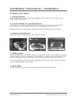
Страница 17: ...gset down using the location of the front feet as pivot points Logset correctly positioned Logset will look like picture shown when installed correctly 1 2 3 1 2 3 Adding granules Gently place granules in front of the main log Level it with a pencil or screwdriver and remove excess material Do not pour granules as dust particles from plastic bag may block the burner ports If the logset is to be re...

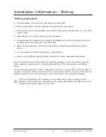
Страница 18: ...n the heater on and off a few times to check ignition When you are satisfied that the heater is working correctly reassemble the panels All burner aerations are factory preset and cannot be adjusted If you are unable to get the unit to operate correctly refer to troubleshooting section of this manual before contacting Rinnai It may take approximately 2 hours of operation for the logs to achieve th...

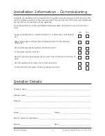
Страница 19: ...d gas pressures been checked and set Is the logset located correctly Have the granules been placed evenly and on top of the burner and free of dust Has the appliance been tested for correct operation Is the customer fully aware of the operating procedure Installer Details Company name ______________________________________________________________ Installer name ____________________________________...

Страница 20: ...ai co nz and www rinnai tradesmart co nz Wiring Diagram 1 1 2 BL 2 1 220 240 v 50 Hz BR G Y BL W W BL BL W IGN SWITCH MICR O BL SPAR KER ELECTRODE FAN 2 BR FAN SWITCH ON OFF THE R MAL 1 2 3 R BL BL R W FAN SWITCH HI LOW MICR O W S V OHS TC W R Red BL Blue BR Brown W White G Y Green Yellow OHS Overheat Switch SV Solenoid Valve TC Thermocouple If the supply cord is damaged or requires replacing it m...

Отзывы: