background image

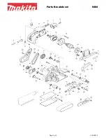
PARTS LIST   2 of 2

Page 22

1

1

2

1

1

1

1

1

1

1

1

1

2

2

1

3

3

1

1

1

1

1

1

1

1

51

52

53

54

55

56

57

58

59

60

61

62

63

64

65

66

67

68

69

70

71

72

73

74

75


Adjusting Spring

Rubber W

asher

Big Flat W

asher     D6

Cotter Pin               2x10

Pin                          5x10

Fix Shaft

Tension Handle

Disc Right Support

Disc Left Support

Sleeve

Phillips Screw+Lock W

asher+Big Flat W

asher

 M

5x

16

Pull Spring

Phillips Screw    M5x25

Phillips Screw    M5x16

Belt Cover

Phillips Screw+Spring W

asher+Flat W

asher  M4x8

Pointer

Belt

W

rench      S5

Left End Cap

Right End Cap

Plug

Strain Relief     6P4

Disc W

asher

Disc Paper

KEY

             DESCRIPTION                                            QTY

        MFG. 

NO.                                                                                              P

ART NO.

P50-1

14-51

P50-1

14-52

P50-1

14-53

P50-1

14-54

P50-1

14-55

P50-1

14-56

P50-1

14-57

P50-1

14-58

P50-1

14-59

P50-1

14-60

P50-1

14-61

P50-1

14-62

P50-1

14-63

P50-1

14-64

P50-1

14-65

P50-1

14-66

P50-1

14-67

P50-1

14-68

P50-1

14-69

P50-1

14-70

P50-1

14-71

P50-1

14-72

P50-1

14-73

P50-1

14-74

P50-1

14-75

5

1

1

3

1

1

1

1

1

1

1

1

1

1

1

4

1

1

3

3

1

1

2

1

1

76

77

78

79

80

81

82

83

84

85

86

87

88

89

90

91

92

93

94

95

96

97

98

99

100

Phillips Screw+Flat W

asher      M4x8

Disc 

W

ork T

able

Miter Gauge Pointer

Knob

Phillips Screw+Spring W

asher+Flat W

asher M5x8

Miter Gauge Knob

Disc Dust Port

Miter Gauge

Miter Gauge Bar

Capacitor           20μF300V

Capacitor Support

Hex Nut          M8

Disc Plate

Flat Key         C4.8*15

Phillips Screw       M6*16left

Phillips Screw       3.5*9.5

Left 

Table Baffle Plate

Right 

Table Baffle Plate

Hex Bolt             M6*14

Hex Flange Nut         M6

Belt 

W

ork T

able

W

ork T

able 

Support

Phillips Screw+Flat W

asher   M4x8

Disc Cover

Open End W

rench

P50-1

14-76

P50-1

14-77

P50-1

14-78

P50-1

14-79

P50-1

14-80

P50-1

14-81

P50-1

14-82

P50-1

14-83

P50-1

14-84

P50-1

14-85

P50-1

14-86

P50-1

14-87

P50-1

14-88

P50-1

14-89

P50-1

14-90

P50-1

14-91

P50-1

14-92

P50-1

14-93

P50-1

14-94

P50-1

14-95

P50-1

14-96

P50-1

14-97

P50-1

14-98

P50-1

14-99

P50-1

14-100

KEY

             DESCRIPTION                                          QTY

         MFG. 

NO.                                                                                             P

ART NO.

NOTE: 

Please reference the Manufacturer

’s Part Number when calling for Replacement Parts. 

For Parts under W

arranty

, the Serial Number of your machine is required.

Содержание 50-114

Страница 1: ...purchase in your manual for future reference The serial number can be found on the specification label on the rear of your machine Serial Number ___________________________ Date of purchase __________...

Страница 2: ...to provide you with the guidelines for the proper safety assembly and operation of this machine PAGE SECTION SAVE THESE INSTRUCTIONS Refer to them often This owner s manual is not a teaching aid and...

Страница 3: ...e tool read and follow all of the Safety and Operating Instructions before operating the Bench Sander 1 Some dust created by using power tools contain chemicals known to the State of California to cau...

Страница 4: ...h it Page 4 19 MAINTAIN YOUR BALANCE DO NOT extend yourself over the tool Wear oil resistant rubber soled shoes Keep floor clear of debris grease and wax 20 MAINTAIN TOOLS WITH CARE Always keep tools...

Страница 5: ...GROUNDED WHILE IN USE TO PROTECT THE OPERATOR FROM ELECTRIC SHOCK IN THE EVENT OF A MALFUNCTION OR BREAKDOWN grounding provides the path of least resistance for electric current and reduces the risk...

Страница 6: ...SANDERS This machine is intended for the surfacing of natural solid woods and composite materials Any other use not as specified including modification of the machine or use of parts not tested and ap...

Страница 7: ...etween the sanding disc or the sanding belt and their tables See Mounting Disc Table instructions on page 10 19 Always support the workpiece with the table or backstop during sanding 20 Carefully feed...

Страница 8: ...y identification and assembly If any parts are missing or broken please call RIKON Customer Service 877 884 5167 as soon as possible for replacements DO NOT turn your machine ON if any of these items...

Страница 9: ...T 8 DIAMETER PSA SANDING DISC TABLE LOCKING LEVER HANDLE ANGLE SCALE TABLE LOCKING LEVER HANDLE ANGLE SCALE TABLE LOCKING LEVER HANDLE ANGLE SCALE BELT TABLE DUST PORT DUST PORT MOUNTING HOLE MOUNTING...

Страница 10: ...s E 3 Place a washer B on the threaded shafts of each worktable handle A insert the handle shafts through the semi circu lar slots D and tighten into the threaded holes E on both sides of the table 4...

Страница 11: ...om 0 to 60 right or left for angle or miter sanding 1 Install the miter gauge bar B into the table slot C as shown 2 Loosen lock knob D and then rotate miter gauge body to the desired angle 3 Tighten...

Страница 12: ...E and secure the scale pointer F at 0 NOTE The disc table B can be tilted from 0 to 45 by loosening the table lock knob D Tilt the disc table to the desired angle then tighten the table lock knob ADJ...

Страница 13: ...ZONTAL SANDING Your belt disc sander belt station can sand vertically as well as horizontally Depending on operator needs and the workpiece the worktable can be used with either the horizontal or vert...

Страница 14: ...dust collector when using this belt disc sander Use of a mask or respirator is still recommended even when a dust collection system is in use NOTE Do not operate the sander without first turning on t...

Страница 15: ...her conditions that may affect the operation Should any of these conditions exist do not use the sander until properly repaired or parts are replaced REPLACING THE SANDING DISC Use only sanding discs...

Страница 16: ...ety disc cover back onto the machine REPLACING THE SANDING BELT 1 Remove the belt worktable See page 10 and 11 for reference 2 Remove the belt sander support rod A See page 14 for reference 3 Position...

Страница 17: ...nd up on the wheels causing them to slip Turn the power switch OFF and disconnect the plug from the outlet prior to adjusting or maintaining the sander DO NOT attempt to repair or maintain the electri...

Страница 18: ...TE WHITE MAIN WINDING SECOND WINDING RELAY RELAY DIAGRAM START CAPACITOR RUN CAPACITOR SANDING DISCS 8 Diameter PSA Aluminum Oxide 50 8060 60 Grit Pack of 5 50 8080 80 Grit Pack of 5 50 8120 120 Grit...

Страница 19: ...r line overloaded with lights other tools etc 2 Long wrong extension cord being used 3 Incorrect fuses or circuit breakers in power cord 1 Reduce the load on power line 2 Replace with correct extensio...

Страница 20: ...IAGRAM 50 114 4 x 36 BELT 8 DISC SANDER Page 20 NOTE Please reference the Manufacturer s Part Number when calling for Replacement Parts For Parts under Warranty the Serial Number of your machine is re...

Страница 21: ...114 21 P50 114 22 P50 114 23 P50 114 24 P50 114 25 4 1 2 1 1 2 1 1 1 1 1 1 1 8 1 1 2 1 2 2 1 1 3 1 1 26 27 28 29 30 31 32 33 34 35 36 37 38 39 40 41 42 43 44 45 46 47 48 49 50 Rubber Foot Belt Dust P...

Страница 22: ...1 1 1 1 1 1 1 1 1 1 1 4 1 1 3 3 1 1 2 1 1 76 77 78 79 80 81 82 83 84 85 86 87 88 89 90 91 92 93 94 95 96 97 98 99 100 Phillips Screw Flat Washer M4x8 Disc Work Table Miter Gauge Pointer Knob Phillips...

Страница 23: ...RANTY To register your machine online visit RIKON at www rikontools com warranty To take advantage of this warranty or if you have any questions please contact us at 877 884 5167 or email warranty rik...

Страница 24: ...www rikontools com 50 114M1 50 114 For more information 16 Progress Road Billerica MA 01821 877 884 5167 978 528 5380 techsupport rikontools com...

Отзывы: