
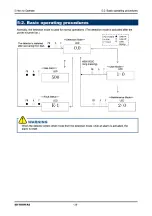


6 Operations and Functions
6-2. Fault alarm activation
- 37 -
SD-1DGH-AS
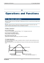
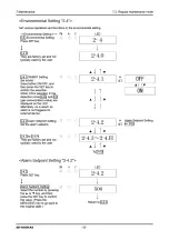
<Response to Gas Alarm>
A gas concentration value exceeds the alarm setpoint
When a gas alarm is triggered, take actions in accordance with your management rules of gas alarm.
Normally, take the following actions.
Check the reading of the detector.
NOTE
If a gas leak is momentary, the reading may already have dropped when checking it. In addition, when the
alarm is triggered by noise or other incidental conditions other than a gas, the reading may have already
dropped.
Based on your management rules of gas alarm, no one can be allowed to access the monitored zone to
ensure safety.
If the gas concentration display continues to be displayed, close the main valve of the gas, and then
check that the gas concentration reading dropped.
Access the gas leak point, equipped with a protective gear to avoid dangers caused by possibly
remaining gases, and check whether gases remain or not by using a portable gas detector.
Check that the point is free from dangers, and take actions to fix the gas leak.
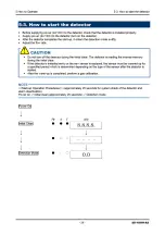
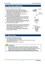
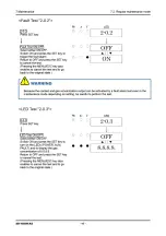
6-2. Fault alarm activation
A fault alarm is triggered when the detector detects abnormalities. After a fault alarm is triggered, the fault
lamp (yellow) lights up and an error message is displayed on the LED. Determine the causes and take
appropriate actions.
After the detector is successfully returned from the fault, it restarts with the process normally performed right
after it is turned on (initial clear).
If the detector has problems and is repeatedly malfunctioning, contact RIKEN KEIKI immediately.
NOTE
For information on malfunctions (error messages), see "9. Troubleshooting".
Содержание PT2-169
Страница 1: ...PT2E 2525 Smart Transmitter Gas Detector Head SD 1DGH AS Operating Manual PT2E 170 PT2 170...
Страница 4: ......
Страница 8: ......
Страница 9: ......
Страница 10: ......
Страница 12: ......
Страница 15: ......
Страница 19: ......
Страница 20: ......
Страница 22: ......
Страница 23: ......
Страница 24: ......
Страница 28: ......
Страница 29: ......
Страница 32: ......
Страница 33: ......
Страница 34: ......
Страница 35: ......
Страница 38: ......
Страница 43: ......
Страница 45: ......
Страница 46: ......
Страница 47: ......
Страница 48: ......
Страница 49: ......
Страница 50: ......
Страница 51: ......
Страница 52: ......
Страница 53: ......
Страница 60: ...10 Product Specifications 10 1 List of specifications SD 1DGH AS 60 Adapter A NPT1 2 Adapter B NPT3 4...
Страница 62: ...10 Product Specifications 10 1 List of specifications SD 1DGH AS 62 Outline Drawings...
Страница 65: ......