Operating Manual
06
/202
2
-Di.
Subject to modifica
tions
Page 3 of 5
Breite: 170
Höhe:8,15
Oben Links
278,5 20
RIFOX - Hans Richter GmbH Spezialarmaturen Fon: +49 (0) 421 499 75 - 0 Internet: www.rifox.de
Bertha-von-Suttner-Str. 9 D-28207 Bremen Fax: +49 (0) 421 499 75 - 40 Email: [email protected]
2.8
Gastight under-level float control (only for gas applications)
■
For gas applications, a gastight under-level float control is nearly
exclusively used.
■
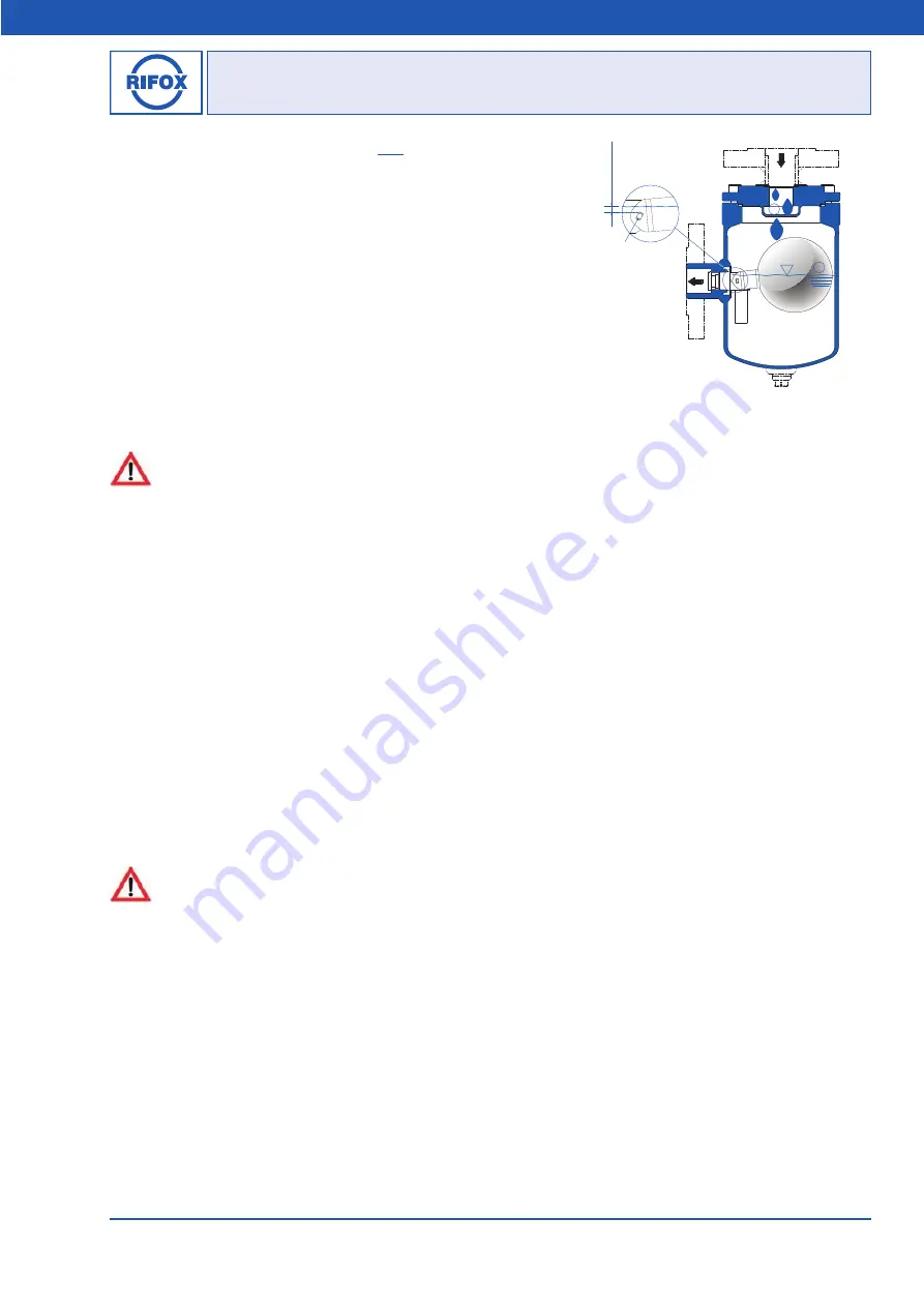
The condensate trap must be filled with water before start-up.
The required water trap is automatically adjusted during the proper
operation. (Picture 5, Point
①
) The water trap is shown as dimension X
in Picture 5.
■
The permanent presence of the minimum condensate level in the
condensate trap is a prerequisite for the complete gas tightness. When
the condensate level sinks under the cross-section (water seal does not
exist), the gas tightness is no longer guaranteed.
■
To ensure permanent gas tightness, it is required that condensate
always drops in the condensate trap. (Picture 5, Point
②
) If there are
for hours or days no condensate, gas may leak through the closed valve.
■
The pressure peaks are absorbed by the condensate trap.
When using submerged-gastight control units, please note:
The valve orifice is always under an condensate surface.
If the gas is mixed or dissolved with the condensate, there can be no separation inside the steam trap.
Small amounts of gas can separate from the condensate at the outlet.
In these cases a degassing line at the outlet towards uncritical areas (via the roof for example) may be recommended.
A horizontal inflow can calm the condensate flow and support the self-degassing to separate the gas from the condensate.
When using an angular version (EF) condensate enters from above and can also bring gas into the housing.
With an inlet from below, the degassing happen before the trap, the automatic degassing is most effective.
Traps with submerged-gastight control units should not be used at above 90°C or its use should be clarified with RIFOX in
advance.
3 Installation
The steam trap can be flanged screwed or flanged into a pipeline between flanges.
■
Remove protective caps from inlet and outlet.
■
Fitting position:
according to Picture 1, 2 and 3.
■
To avoid downtimes, it is recommended that provision be made for a shut-off device with a bypass line both in front of and
behind the steam trap.
4 Start-Up
The pressure build-up and heating-up of the housing should not take place abruptly. If leakage is detected after the first
inspection, the screws (4 / 6 / 8 / 9) can be fixed under consideration of the given torque moments, as given in Section 6.5.
The screws can only be tightened on when the housing is unpressurized and T<50°C.
5
Observation and control
The function’s failure can be observed either as condensate blockage or as gas/ steam leakage.
■
Condensate blockage
can be determined by a): loosen the control screw (6) for a quarter rotation, while no condensate
leakage should occur; and by b): a surface thermometer on the housing for steam applications (if necessary, consult with
Rifox).
■
Gas / steam leakage:
can be determined by an ultrasonic measuring device, and for steam applications by a surface
thermometer. In case of steam leakage, open the condensate trap according to Section 6.1. Make sure that float can be easily
moved. If necessary, disassemble and clean the float control assembly (5). If damages/ wears are detected on parts or on the
sealing surface, the complete float control assembly (5) should be replaced.
1
Min.
2
Picture 5
X:
W
ater
tra
p
Cross Section


