


22
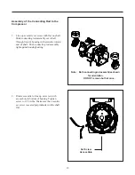
5. Place the head on the valve plate assemblies
observing the position of the air intake and
exhaust ports.
Note: Make sure the head gasket O-rings are not
pinched.
6. Insert the head screws and finger tighten each
screw until it is snug.Use a Torx® T-25 driver
to tighten each head screw to 55 inch-
pounds, in the sequence shown.
Caution
To avoid property damage or personal
injury, always try rotating the fan by
HAND, prior to connecting the unit to
the power source. Check for suction at
the air inlet port by placing your finger
over the port as you turn the fan. You
should feel a slight suction with each
rotation of the fan. If you don't feel
suction, or if you feel or hear a thump
as you turn the fan, DO NOT
CONNECT THE UNIT TO A POWER
SOURCE; review the assembly
procedure for possible error.
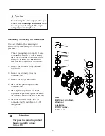
Servicing the Fan
If one or both of the fans break, use the following
procedure:
1. Carefully remove the fan by pulling it straight
off the motor shaft.
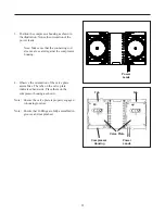
2. Align the flat on the motor shaft with the flat
on the fan and slide the fan back onto the
motor shaft, making sure the fan clip (1) faces
as shown.
Numbers indicate tightening sequence
5
3
4
6
2
8
7 1
Intake
Exhaust
Opposite Lead Side
Clip Toward
Compressor
Clip Toward
Compressor


