


20068118
38
GB
Start-up, calibration and operation of the burner
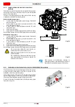
6.7.0.1 Procedure for inserting and adjusting points on
the modulation curve
Nine adjustment/calibration points (P1 ÷ P9) can be inserted in
the control box for each servomotor, varying their position by de-
grees and, consequently, the quantity of air and fuel introduced.
The
ignition point P0
is independent of the minimum modulation
value. This means that, in the event of difficulty, it is possible to
switch on the burner at a value other than the modulation mini-
mum (
P1
).
To access the
Parameter mode
(group 400) referring to the
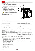
To insert or adjust a point, proceed as follows.
Using the keys
“+”
and
“-”
insert/select the curve point you want
and wait for it to flash: this means that the servomotors are now
positioned on the values shown on the display and which corre-
spond to the point previously set.
It is now possible to insert/modify the position by degrees.
For the fuel servomotor, keep the key
“F”
pressed (the position
in degrees flashes) and press the keys
“+”
or
“-”
to increase or
decrease the value.
For the air servomotor, keep the key
“A”
pressed (the position in
degrees flashes) and press the keys
“+”
or
“-”
to increase or de-
crease the value.
To adjust the speed of the inverter (expressed in
%
and that is
50
Hz = 100 %
), keep the buttons
“F”
and
“A”
simultaneously
pressed, the percentage position blinks and press buttons
“+”
or
“-”
to increase or decrease the value.
Select another point, or exit this area by pressing the keys
“+”
and
“-”
(
ESC
) simultaneously.
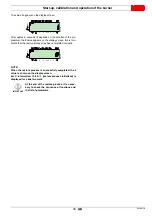
6.7.0.2 CALC function
The diagram (Fig. 36) shows how the fuel modulation curve is
modified if the values of point “
P5
” are changed.
By keeping the
“+”
key pressed for more than 3s, the points
from “
P6
” to “
P8
” are recalculated.
By keeping the
“-”
key pressed for more than 3s, the points from
“
P4
” to “
P2
” are recalculated.
The diagram of (Fig. 37) shows the fuel modulation curve when,
after the modification of point “
P5
”, the recalculation of all the oth-
er points is not carried out.
WARNING
The set value does not require confirmation.
D
9032
P
min
h
s
%
V
D
9033
P
s
%
F
D
9034
P
V
min
h
A
D
12135
h min
%
P
V
VSD
A
F
ESC
Fig. 36
P0
P1
P2
P3
P4
P5
P6
P7
P8
P9
0
10
20
30
40
50
60
70
80
90
100
An
gle (degrees)
Point of the curve
original
curve
CALC-
CALC+
D7908
Recalculation
Fu
el
Fig. 37
P0
P1
P2
P3
P4
P5
P6
P7
P8
P9
0
10
20
30
40
50
60
70
80
90
100
Point of the curve
Angle (degre
e
s
)
D7909
Fu
el
Содержание RS 25/E BLU Series
Страница 2: ...Translation of the original instructions...
Страница 65: ...63 20068118 GB Appendix Electrical panel layout RS 25 E BLU...
Страница 66: ...20068118 64 GB Appendix Electrical panel layout RS 35 E BLU...
Страница 67: ...65 20068118 GB Appendix Electrical panel layout RS 35 E BLU 3Ph...
Страница 68: ...20068118 66 GB Appendix Electrical panel layout RS 25 35 E BLU...
Страница 69: ...67 20068118 GB Appendix Electrical panel layout RS 35 E BLU 3Ph...
Страница 70: ...20068118 68 GB Appendix Electrical panel layout...
Страница 71: ...69 20068118 GB Appendix Electrical panel layout...
Страница 72: ...20068118 70 GB Appendix Electrical panel layout...
Страница 73: ...71 20068118 GB Appendix Electrical panel layout...
Страница 75: ......


