


19
20148107
GB
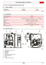
Electrical system
7.2
Example of an electrical system without heater
Capacitor
E
Ignition electrodes
F
Flame sensor
MV
Fan motor
P
Short circuit socket
RS
Remote reset
SB
Remote lock-out signal (230V - 0.5A max)
TB
Burner earth
TL
Heat request thermostat
TS
Safety thermostat
V
Oil valve
XP5 5- pole socket
X5
5 pin plug
~ 50Hz - 230 V
CONTROL BOX
White
Gre
en/Yell
ow
Blue
Black
White
Black
Red
Grey
20068692
T4A
General
switch
TO BE DONE BY
THE INSTALLER
CARRIED OUT
IN THE FACTORY
Fig. 4
WARNING
Do not invert the neutral with the phase in the
electrical supply line.
Check that the electrical supply of the burner
corresponds to that shown on the identifica-
tion label and in this manual.
The section of the conductors must be at
least 1mm
2
. (Unless otherwise required by
local guidelines and laws).
WARNING
Test the burner by checking the shut-down of the
burner by opening the thermostats and the lockout
by darkening the flame sensor.
CAUTION
If the hood is still present, remove it and pro-
ceed with the electrical wiring according to
the wiring diagrams.
Use flexible cables in compliance with the EN
60 335-1 standard.


