


‐
24
‐
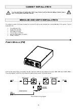
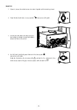
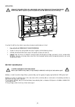
CABINET INSTALLATION
For the installation of the Modular UPS Power Cabinet and the Modular Battery Cabinet please
refer to the specific installation manual.
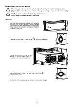
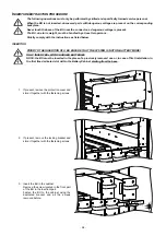
MODULES AND UNITS INSTALLATION
The cabinet consists of hot-swap modules and units which allow quick maintenance and expandability of the system. The hot-
swap parts are:
Power Module (PM)
Bypass Module (BM)
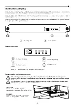
Monitoring Unit (MU)
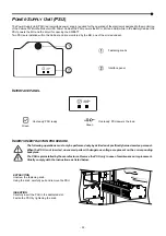
Power Supply Unit (PSU)
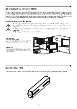
Main Communication Unit (MCU)
Battery Unit (BU)
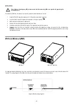
P
OWER
M
ODULE
(PM)
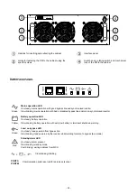
The Power Module (PM) is a three-phase double-conversion UPS module available in two sizes: 25kW (PM25) and 42kW (PM42).
The wiring diagram of the PM, which shows its individual components, is provided below:
Power Module wiring diagram
Содержание multipower BTC 170
Страница 1: ......
Страница 2: ......
Страница 6: ...6...
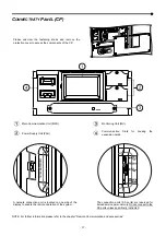
Страница 8: ...8 GENERAL VIEWS Front view Back view Frame Handle with lock Door Back Panel...
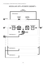
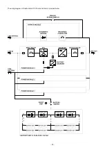
Страница 20: ...20 The wiring diagram of the Modular UPS Power Cabinet is provided below...
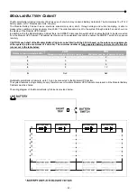
Страница 23: ...23 The wiring diagram of the Modular UPS Combo Cabinet is provided below...
Страница 54: ...54 Combo Cabinet...
Страница 55: ...55 Battery Cabinet...
Страница 82: ......
Страница 83: ......
Страница 84: ...0MNMPWK25R1ENUA...