


‐
29
‐
I
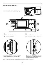
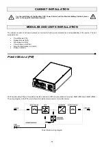
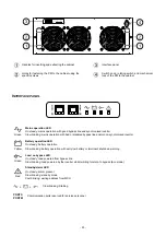
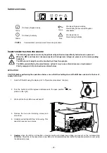
NTERFACE PANEL
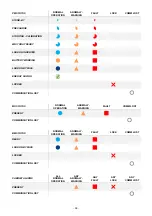
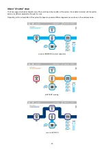
Green
On steady:
Bypass ready
Green
On steady
: Bypass working
Slow blinking
: active call with bypass
unavailable
Yellow
On steady
: Anomaly
Red
On steady
: Alarm
Slow blinking
: Initialize
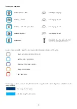
PORT S
Communication ports reserved for service personnel
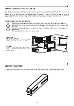
I
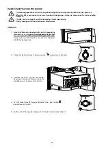
NSERTION
/
EXTRACTION PROCEDURE
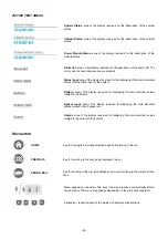
The following operations must only be performed by skilled and specifically trained service personel.
When the BM is not inserted, uncovered parts with dangerous voltage are present on the corresponding
backplane.
The BM, due to its weight, must be handled by at least two people.
The BM is preinstalled by the manufacturer, extract it only in case of maintenance or replacement.
Strictly comply with the instructions as listed below.
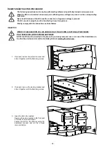
EXTRACTION
CAUTION: Before performing the operations below, ensure that the shutting down of the BM does not lead to the loss of
supply to the load.
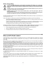
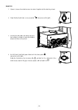
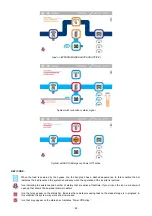
1. Switch off the BM using the display (ref. to “Operative procedures” chapter).
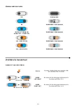
2. Turn the Switch Lock 90 degrees anticlockwise to the open position
(see
picture on the right).
3. Wait until the front LEDs are switched off.
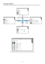
4. Remove the two side fastening screws and
store them.
5. Carefully extract the BM from its housing. This
operation requires two persons.
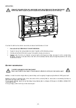
6.
Caution
: when the BM is not inserted, uncovered parts with dangerous voltage are present on the corresponding
backplane. Therefore, in the case where a new BM is not immediately inserted, install the supplied protection cover using
the dedicated screws.
Содержание multipower BTC 170
Страница 1: ......
Страница 2: ......
Страница 6: ...6...
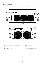
Страница 8: ...8 GENERAL VIEWS Front view Back view Frame Handle with lock Door Back Panel...
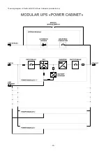
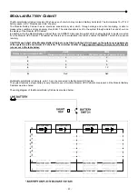
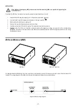
Страница 20: ...20 The wiring diagram of the Modular UPS Power Cabinet is provided below...
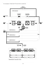
Страница 23: ...23 The wiring diagram of the Modular UPS Combo Cabinet is provided below...
Страница 54: ...54 Combo Cabinet...
Страница 55: ...55 Battery Cabinet...
Страница 82: ......
Страница 83: ......
Страница 84: ...0MNMPWK25R1ENUA...