


Start-up, calibration and operation of the burner
29
20102152
GB
5.1
Notes on safety for the first start-up
5.2
Operations before start-up
Ensure that the gas supply company has carried out the sup-
ply line vent operations, eliminating air or inert gases from the
piping.
Slowly open the manual valves situated upstream of the gas
train.
Adjust the minimum gas pressure (Fig. 39) switch to the start
of the scale.
Adjust the maximum gas pressure switch (Fig. 38) to the end
of the scale.
Adjust the air pressure switch (Fig. 36) to the start of the scale.
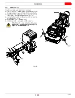
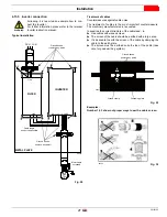
Purge the air from the gas line. Fit a U-type manometer
(Fig. 34) to the gas pressure test point on the sleeve.
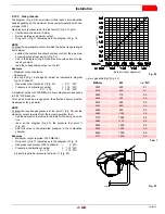
The manometer readings are used to calculate the MAX.
burner power using the diagram on page 23.
5.3
Burner start-up
Feed electricity to the burner via the disconnecting switch on the
boiler panel.
Close the thermostats/pressure switches, set the parameters on
the RWF55 regulator.
Please refer to the specific manual for this operation.
Turn the switch of Fig. 35 to position
“ON”
and turn the switch of
“LOCAL”
.
5
Start-up, calibration and operation of the burner
WARNING
The first start-up of the burner must be carried out
by qualified personnel, as indicated in this manual
and in compliance with the standards and regula-
tions of the laws in force.
WARNING
Check the correct working of the adjustment, com-
mand and safety devices.
CAUTION
Before starting up the burner it is good practice to
adjust the gas train so that ignition takes place in
conditions of maximum safety, i.e. with gas delivery
at the minimum.
Fig. 34
D2368
DANGER
Make sure that the lamps or testers connected to
the solenoids, or indicator lights on the solenoids
themselves, show that no voltage is present.
If voltage is present, stop the burner
immediately
and check the electrical wiring.
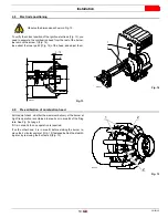
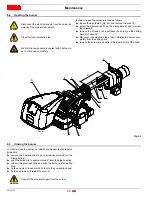
When the burner starts, check the direction of the
motor rotation, as indicated in Fig. 35.
REMOTE
LOCAL
ON OFF
Fig. 35
20097538


