


Installation
19
20102152
GB
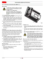
4.8
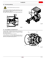
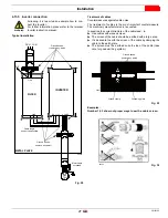
Electrode positioning
To verify the correct position of the ignition electrode (Fig. 13), you
need to separate the combustion head from the rest of the burner:
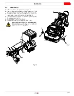
remove the screw 1)(Fig. 14);
extract the inner part 2)(Fig. 14) of the head, and adjust them.
4.9
Pre-calibration of combustion head
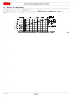
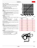
At this point check, whether the maximum delivery of the burner at
high fire operation is contained in area A) or in area B) of the firing
rate. See Fig. 3 at page 8.
If it is in area A) then no operation is required.
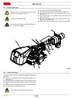
If on the other hand, it is in area B, before starting the burner re-
move the 4 circular sectors 1)(Fig. 15) fastened behind the stabiliz-
ing disc by removing the 8 screws 2)(Fig. 15).
WARNING
Observe the dimensions shown in Fig. 13.
1 / 8 "
5 / 1 6 "
Fig. 13
D10692
2
1
Fig. 14
D10592
Fig. 15
D2382
2
2
1


