background image

35

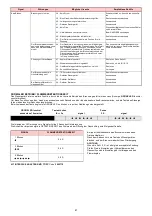
ENDKONTROLLEN

 (bei Brenner in Betrieb)

• Einen  Draht  des  Gas-Mindestdruckwächters

abtrennen.

• Fernsteuerung TL abschalten.
• Fernsteuerung TS abschalten:
der Brenner muß anhalten

• Den Luftzuleitungsschlauch zum Druckwächter

am positiven Pol (+) abtrennen Abb. A S. 30.

• Draht des Ionisationsfühlers abtrennen: 
Der Brenner muß in Störabschaltung anhalten

• Überprüfen,  ob  die  mechanischen  Sperren

der Einstellvorrichtungen fest angezogen sind .

WARTUNG

Der Brenner erfordert eine periodische
Wartung, die durch befähigtes Personal
u n d   i n   Ü be r e in s t im m u n g  m i t  de n
örtlichen  Gesetzen und Vorschriften
auszuführen ist.

Die  periodische  Wartung  ist  für  einen
korrekten Brennerbetrieb sehr wichtig
u n d  

v e r h i n d e r t  

s o  

u n n ü t z e n

Brennstoffverbrauch und reduziert die
Schadstoffemissionen in die Umwelt.

Vor Reinigungs- oder Kontrollvorgängen
i m m e r   d i e   S t r o m v e r s o r g u n g   z u m
B r e n n e r   d u r c h   B e t ä t i g u n g   d e s
Hauptschalters der  Anlage abschalten.

Verbrennung

Die  Abgase  der  Verbrennung  analysieren.
Bemerkenswerte  Abweichungen  im  Vergleich
zur  vorherigen  Überprüfung  zeigen  die  Stelle
an,  wo  die  Wartung  aufmerksamer  ausgeführt
werden soll.

Gasundichtigkeiten
Die  Zähler-Brenner-Leitung  auf  Gasundichtig-
keiten kontrollieren.

Gasfilter
Verschmutzten Gasfilter austauschen.

Flammensichtfenster
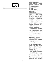
Das Sichtfenster (A) putzen.

Flammkopf
Den  Brenner  öffnen  und  überprüfen,  ob  alle
Flammkopfteile  unversehrt,  nicht  durch  hohe
Temperatur verformt, ohne Schmutzteile aus der
Umgebung und richtig positioniert sind. Im Zwei-
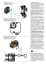
felsfall den Bogen 7)(B) ausbauen. 

Stellantrieb
Den  Nocken  4)(A)S.28  durch  90°  Drehung  des
Schlitzes 2)(A)S.28 vom Stellantrieb entsperren,
und von Hand die ungehinderte Drehbewegung
nach  vorne  und  hinten  prüfen.  Den  Nocken
4)(A)S.28 wieder sperren.

Brenner
Es  ist  zu  überprüfen,  ob  ungewöhnlicher  Ver-
schleiß  oder  die  Lockerung  der  Schrauben  in
den Antriebselementen der Luftklappe und Gas-
drossel  vorliegen.  Die  Schrauben  zur  Befesti-
gung  der  Kabel  am  Brennerklemmenbrett
müssen festgezogen sein.
Den  Brenner,  besonders  die  Gelenke  und  den
Nocken 4)(A)S.28, von außen reinigen. 

Verbrennung
Falls  die  anfänglich  festgestellten  Verbren-
nungswerte nicht mit den geltenden Vorschriften
übereinstimmen, oder jedenfalls nicht einer kor-
rekten  Verbrennung  entsprechen,  muß  der
Brenner neu eingestellt werden.
Tragen Sie auf einem geeigneten Formular  die
neuen  Verbrennungswerte  ein,  die  für  spätere
Kontrollen nützlich sind.

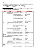
FINAL CHECKS

 (with burner running)

• Disconnect one of the wires on the minimum

gas pressure switch.

• Open remote control device TL.
• Open remote control device TS:
the burner must stop

• Detach  the  air  feed  pipe  to  the  pressure

switch in positive mode (+) fig. A page 30.

• Disconnect the ionisation probe lead: 
the burner must lock out

• Make  sure  that  the  mechanical  locking  sys-

tems  on  the  various  adjustment  devices  are
fully tightened.

MAINTENANCE

T h e   b u r n e r   r e q u i r e s   p e r i o d i c
maintenance carried out by a qualified
and authorised technician in conformity
with legislation and local standards
.

Periodic maintenance is essential for the
reliability  of  the  burner, avoiding the
e xce ss ive   co n su mp ti o n   o f   fu e l   a n d
consequent pollution.

Before   carrying  out  any  cleaning  or
control, always switch off the electrical
supply  to  the burner,  using  the main
switch of the system.

Combustion
The  optimum  calibration  of  the  burner  requires
an analysis  of the  flue  gases. Significant  differ-
ences  with  respect  to  the  previous  measure-
ments  indicate  the  points  where  more  care
should be exercised during maintenance.

Gas leaks
Make  sure  that  there  are  no  gas  leaks  on  the
pipework between the gas meter and the burner.

Gas filter
Change the gas filter when it is dirty.

Flame inspection window
Clean the flame inspection window (A).

Combustion head
Open the burner and make sure that all compo-
nents of the combustion head are in good condi-
tion,  not  deformed  by  the  high  temperatures,
free of impurities from the surroundings and cor-
rectly  positioned.  If  in  doubt,  disassemble  the
elbow fitting 7)(B).

Servomotor
Disengage the cam 4)(A)p.28 from servomotor,
by turning slot 2)(A)p.28 through 90° and turn it
backward and forward by hand to make sure it is
free moving. Now engage cam 4)(A)p.28 again.

Burner
Check  for  excess  wear  or  loose  screws  in  the
mechanisms  controlling  the  air    gate  valve  and
the gas butterfly valve. Also make sure that the
screws  securing  the  electrical  leads  in  the
burner terminal strip are fully tightened.
Clean  the  outside  of  the  burner,  taking  special
care  with  the  transmission  joints  and  cam
4)(A)p.28. 

Combustion
Adjust the burner if the combustion values found
at the beginning of the operation do not comply
with  the  regulations  in  force,  or  at  any  rate,  do
not  correspond  to  good  combustion.  Use  the
appropriate  card  to  record  the  new  combustion
values;  they  will  be  useful  for  subsequent  con-
trols.

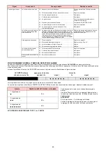
CONTROLES  FINAUX

  (brûleur  en  fonction-

nement)
• Débrancher un fil du pressostat de seuil mini-

mum gaz.

• Ouvrir la télécommande TL.
• Ouvrir la télécommande TS:
le brûleur doit s'arrêter

• Détacher le tuyau d’arrivée d’air au pressostat

en positif (+) fig. A pag. 30.

• Débrancher le fil de la sonde d'ionisation: 
le brûleur doit se bloquer

• Contrôler  si  les  blocages  mécaniques  des

dispositifs de réglage sont bien serrés.

ENTRETIEN

Le brûleur nécessite d’un entretien pério-
dique,  qui  doit  être  effectué  par  du  per-
sonnel  expérimenté  et  conformément
aux  lois  et  aux  réglementations
locales.

L’entretien  périodique  est  essentiel  pour
le bon fonctionnement du brûleur ; il évite
ainsi  une  consommation  inutile  de  com-
bustible  et  réduit  les  substances  pol-
luantes dans l’atmosphère.

Avant  d’effectuer  une  opération  de  net-
toyage  ou  de  contrôle  quelconque,  cou-
per  le  courant  du  brûleur  en  actionnant
l’interrupteur général de l’installation.

Combustion
Pour  obtenir  un  réglage  optimal  du  brûleur,    il
faut analyser les gaz de la combustion à la sor-
tie de la chaudière. Les différences significatives
par  rapport  au  contrôle  précédent  indiqueront
les  points  où  l'opération  d'entretien  devra  être
plus approfondie.

Fuites de gaz
Contrôler  l'absence  de  fuites  de  gaz  sur  le
conduit compteur-brûleur.

Filtre du gaz
Remplacer le filtre du gaz lorsqu'il est encrassé.

Viseur flamme
Nettoyer la vitre du viseur de flamme (A).

Tête de combustion
Ouvrir le brûleur et contrôler si toutes les parties
de  la  tête  de  combustion  sont  intactes,  si  elles
ne sont pas déformées par les hautes tempéra-
tures,  si  elles  ne  contiennent  pas  d'impuretés
provenant  du  milieu  ambiant  et  si  elles  sont
positionnées  correctement.  En  cas  de  doute,
démonter le coude 7)(B).

Servomoteur
Enlever la came 4)(A)p.28 du servomoteur en fai-
sant pivoter la fente 2)(A)p.28 de 90° et contrôler
manuellement  si  sa  rotation  en  avant  et  en
arrière  se  fait  librement.  Remettre  la  came
4)(A)p.28.

Brûleur
Vérifier qu'il n'y ait pas d'usure anormale ou de
vis  desserrée  dans  les  mécanismes  qui  com-
mandent  le  volet  d'air  et  la  vanne  papillon  du
gaz. De même, les vis qui fixent les câbles à la
plaque à bornes du brûleur doivent être correc-
tement serrées.
Nettoyer l'extérieur du brûleur, en particulier les
rotules et la came 4)(A)p.28. 

Combustion
Régler le brûleur si les valeurs de la combustion
trouvées  au  début  de  l'intervention  ne  satisfont
pas les normes en vigueur ou ne correspondent
pas à une bonne combustion.
Reporter les nouvelles valeurs de la combustion
sur  une  fiche  spéciale;  elles  seront  utiles  pour
les contrôles successifs.

Содержание 882 T80

Страница 1: ...d aria soffiata Gas Gebl sebrenner Forced draught gas burners Br leurs gaz air souffl Funzionamento bistadio progressivo o modulante Zweistufig gleitender oder modulierender Betrieb Progressive two st...
Страница 2: ...14 30 UE Compatibilit Elettromagnetica La qualit viene garantita mediante un sistema di qualit e management certificato secondo UNI EN ISO 9001 Dichiarazione del costruttore RIELLO S p A dichiara che...

Страница 3: ...agnetische Vertr glichkeit Die Qualit t wird durch ein gem UNI EN ISO 9001 zertifiziertes Qualit ts und Managementsystem garantiert Erkl rung des Herstellers Die Firma RIELLO S p A erkl rt dass die fo...

Страница 4: ...ctive EMC 2014 30 UE Electromagnetic Compatibility The quality is guaranteed by a quality and management system certified in accordance with UNI EN ISO 9001 Manufacturer s Declaration RIELLO S p A dec...

Страница 5: ...MC 2014 30 UE Compatibilit lectromagn tique La qualit est garantie gr ce un syst me de qualit et de gestion certifi conforme UNI EN ISO 9001 D claration du constructeur RIELLO S p A d clare que les pr...

Страница 6: ...o cos indicate 1 A Particolare 1 della figura A nella stessa pagina del testo 1 A p 8 Particolare 1 della figura A riportata a pagina 8 I INHALT TECHNISCHE ANGABEN Seite 9 Elektrische daten 9 Brennerb...

Страница 7: ...s text 1 A p 8 part 1 of figure A page number 8 GB INDEX DONNEES TECHNIQUES page 11 Elektrische Daten 11 Description br leur 13 Emballage Poids 13 Encombrement 13 Equipement standard 13 Plage de puiss...

Страница 8: ...8 2 8 13 7 0 Densit assoluta kg Sm3 0 71 0 78 Portata massima Sm3 h 90 104 5 Pressione alla portata massima 2 mbar 15 3 22 5 Funzionamento Intermittente min 1 arresto in 24 ore Due stadi progressivi...

Страница 9: ...2 8 13 7 0 Reindichte kg Sm3 0 71 0 78 H chstdruchsatz Sm3 h 90 104 5 Druck bei H chstleistung 2 mbar 15 3 22 5 Betrieb Intermittierend min 1 Abschaltung in 24 Std Gleitend zweistufig modulierend mit...

Страница 10: ...3 9 45 8 2 8 13 7 0 Absolute density kg Sm3 0 71 0 78 Max delivery Sm3 h 90 104 5 Pressure at max delivery 2 mbar 15 3 22 5 Operation On Off 1 stop min each 24 hours Progressive two stage or modulatin...

Страница 11: ...calorifique inf rieur kWh Sm3 Mcal Sm3 9 45 8 2 8 13 7 0 Densit absolue kg Sm3 0 71 0 78 D bit maximum Sm3 h 90 104 5 Pression au d bit max 2 mbar 15 3 22 5 Fonctionnement Intermittent 1 arr t min en...

Страница 12: ...sonda di ionizza zione 24 Pressostato gas di massima 25 Contattore motore e rel termico con pul sante di sblocco 26 Protezione motore Vi sono due possibilit di blocco del bruciatore BLOCCO APPARECCHIA...

Страница 13: ...ation probe cable 24 Maximum gas pressure switch 25 Motor contact maker and thermal cutout with reset button 26 Engine protection Two types of burner failure may occur CONTROL BOX LOCK OUT if the cont...

Страница 14: ...o 50 cm lunghezza 1 5 m CALDAIE COMMERCIALI C L abbinamento bruciatore caldaia non pone pro blemi se la caldaia omologata CE e le dimen sioni della sua camera di combustione sono vicine a quelle indic...

Страница 15: ...combustion chamber Example Output 350 Mcal h diameter 50 cm length 1 5 m COMMERCIAL BOILERS C The burner boiler combination does not pose any problems if the boiler is CE approved and its combustion...

Страница 16: ...fissata la potenza MAX alla quale si desidera funzioni il bruciatore trovare nella tabella relativa al bruciatore con siderato il valore di potenza pi vicino al valore desiderato Leggere sulla destra...

Страница 17: ...1 This value serves as a rough guide the effective delivery must be measured at the gas meter To calculate the required gas pressure at test point 1 B set the maximim output required from the burner...

Страница 18: ...IA D Prima di fissare il bruciatore alla caldaia verifi care dall apertura del boccaglio se la sonda e l elettrodo sono correttamente posizionati come in D Separare quindi la testa di combustione dal...

Страница 19: ...R D Before securing the burner to the boiler check through the blast tube opening to make sure that the flame sensor probe and the ignition electrode are correctly set in position as shown in D Now de...

Страница 20: ...aria va effettuata sulla tacca 7 5 come in fig A Terminata la regolazione della testa rimontare il bruciatore sulle guide 3 C a circa 100 mm dal manicotto 4 C bruciatore nella posizione illu strata d...

Страница 21: ...of the flange Example MAX output 500 Mcal h If we consult diagram B we find that for this output air must be adjusted using notch 7 5 as shown in figs A Once you have finished setting up the head refi...

Страница 22: ...ta di combustione P2 Pressione a monte valvole regolatore P3 Pressione a monte del filtro L Rampa gas fornita a parte con il codice indicato in tab C L1 A cura dell installatore LEGENDA TABELLA C C T...

Страница 23: ...n accordance with the standard EN 676 gas valve leak detection control devices are compulsory for burners with maximum outputs of more than 1200 kW 8 Gasket 9 Gas adjustment butterfly valve 10 Max gas...

Страница 24: ...che esse siano come sotto riportato Camma I 90 Limita la rotazione verso il massimo Con il bru ciatore funzionante alla potenza MAX la farfalla del gas deve risultare tutta aperta 90 Camma I I 0 Limi...

Страница 25: ...am and the gas butterfly valve The angle of rotation of the servomotor is equal to the angle on the graduated sector controlling the gas butterfly valve The servomotor rotates through 90 in 24 seconds...

Страница 26: ...a spina presa 23 A p 12 sul cavo della sonda di ionizzazione il bruciatore si accende e va in blocco dopo il tempo di sicu rezza Eseguire 10 accensioni con blocchi consecu tivi Leggere al contatore la...

Страница 27: ...quantity of gas burned This quantity must be equal to or lower than the quantity given by the formula for ts 3s Example for gas G 20 9 45 kWh Sm3 ignition output 400 kW corresponding to 47 6 Sm3 h Af...

Страница 28: ...ata d aria svitare le viti 3 POTENZE INTERMEDIE Regolazione del gas Non occorre alcuna regolazione Regolazione dell aria Premere un poco il pulsante 2 A p 26 aumento potenza in modo che una nuova vite...

Страница 29: ...elivery needs to be increased increase outlet gas pressure Adjusting air delivery Progressively adjust the end profile of cam 4 A by turning the cam adjustment screws as they appear through the access...

Страница 30: ...ressostato gas di massima dopo aver effettuato tutte le altre rego lazioni del bruciatore con il pressostato gas di massima regolato a fine scala B Con il bruciatore funzionante alla potenza mas sima...

Страница 31: ...ressure switch after having performed all other burner adjustments with the maximum gas pressure switch set to the end of the scale B With the burner operating at MAX output reduce the adjustment pres...

Страница 32: ...elettrica continua comunque a controllare la presenza della fiamma e la cor retta posizione deI pressostatI aria e gas di massima Se la temperatura o la pressione bassa per cui il termostato pressosta...

Страница 33: ...r temperature control point C The control box continues however to check that the flame is present and that the air pres sure switch is in the correct position If the temperature or pressure is low an...

Страница 34: ...he di gas Controllare che non vi siano fughe di gas sul condotto contatore bruciatore Filtro del gas Sostituire il filtro del gas quando sporco Visore fiamma Pulire il vetrino del visore fiamma A Test...

Страница 35: ...Gas filter Change the gas filter when it is dirty Flame inspection window Clean the flame inspection window A Combustion head Open the burner and make sure that all compo nents of the combustion head...

Страница 36: ...iglia 9 in modo che il bruciatore rimanga in quella posizione A questo punto possibile estrarre il distributore del gas 7 dopo aver tolto la vite 8 PER CHIUDERE IL BRUCIATORE A togliere la copiglia 9...

Страница 37: ...y back Turn the burner as shown in the figure and fit the split pin 9 into one of the slide bar holes so that the burner remains in position Now extract the gas distributor 7 after having removed the...

Страница 38: ...ria mal regolato Regolarlo o sostituirlo 16 Tubetto presa pressione del pressostato ostruito Pulirlo 17 Testa mal regolata Regolarla 18 Alta pressione nel focolare Collegare pressostato aria all aspir...

Страница 39: ...sione del gas in rete vicina al valore sul quale regolato il pressostato gas di minima Il calo di pres sione repentino che segue l apertura della valvola pro voca l apertura temporanea del pressostato...

Страница 40: ...itung der Druckentnahmestelle des Druckw chters verstopft Reinigen 17 Kopf schlecht eingestellt Einstellen 18 Hoher Unterdruck im Feuerraum Luft Druckw chter an Gebl se Ansaug ff nung anschlie en St r...

Страница 41: ...er Gasdruck in der Leitung ist dem am Mindestgas druckw chter eingestellten Wert sehr nahe Der pl tzli che Druckabfall beim ffnen des Ventils bewirkt die ffnung des Druckw chters Dadurch schlie t sich...

Страница 42: ...Air pressure switch incorrectly adjusted Adjust or replace 16 Pressure switch pressure test point pipe blocked Clean 17 Poorly adjusted head Adjust 18 High pressure in the furnace Connect air pressure...

Страница 43: ...s very close to the value to which the minimum gas pressure switch has been set The sudden drop in pressure after valve open ing causes temporary opening of the pressure switch itself the valve immedi...

Страница 44: ...Nettoyer 17 T te mal r gl e R gler 18 Haute pression dans le foyer Raccorder le pressostat air l aspiration du ventilateur Blocage durant la pr ventila tion 19 Contacteur de commande du moteur d fectu...

Страница 45: ...ession du gaz en r seau est proche de la valeur a laquelle le pressostat gaz minimum est r gl La chute de pression soudaine suite l ouverture de la vanne pro voque l ouverture temporaire du pressostat...

Страница 46: ...ere bypassato In caso contrario se si desidera mantenere il termostato pressostato TL la sua regolazione dev essere tale da non interferire col funzionamento del regolatore RWF40 APPENDICE ATTENZIONE...

Страница 47: ...ein dass er den Betrieb des Reglers RWF40 nicht beeinflusst ANHANG ACHTUNG Den Nulleiter nicht mit dem Phasenleiter in der Leitung der Stromversorgung vertauschen Die Folge einer solchen Vertau schung...

Страница 48: ...e switch TL it must be adjusted so as not to interfere with the working of the regulator RWF40 APPENDIX ATTENTION Do not invert the neutral with the phase in the electrical supply line An inversion wo...

Страница 49: ...ontraire maintenu ne doit pas influer sur le fonctionnement du r gulateur RWF40 ANNEXE ATTENTION Dans la ligne d alimentation lectrique ne pas inverser le neutre avec la phase L inversion ventuelle pr...

Страница 50: ...elettrici a cura dell installatore Elektroanschlusse vom Installateur auszuf hren Electrical connections set by installer Raccordements lectriques par l installateur 3 Schema funzionale Betriebsschem...

Страница 51: ...51...

Страница 52: ...1 3 5 G 1 F 4 D 6 I 6 C 6 9 C 6 9 C 6 6 I 9B C 6 7 C B C 7 B J9 I A C J9 C K 9 C A9 6 A I 09B89 C AB99 C 09B C ABL B8 I B C B98 C B A9 C B I 6 7 C 9 C 6 7 C 9 AI B 7 C B A9 C B A9 C B A9 0 I 0 9 C 0 9...

Страница 53: ...5 2 95 3 95 4 0 9 NO54 3 HP3P 877P H76 75Q HP H76 75Q 7 8F G DDR 4 4 4 4 4 4 SH 4H 4H 3 H TJ9 TJ9 3 J H P3P H76 75Q 4 4 J3 3 3 TJ9 TJ9 H U VW J8 H J TJ9 I 39 9 1 3 X X X J Y J4 P J4 P J4 P J4 J Y 3 P...

Страница 54: ...8 928 78 82 2295 87582 297 56 21 28 5 N 3 1528 4 9 9 1 4 215 1 9 295 8 8 9 168 1 4 215 8 P 41 1 1 8 1 61 97248 9521 2 379378 1 6156 Q7 7845O9521O28 1 8 1 46B2 61 1 8 1 C8 61 II 1 8 845 61 O42 R 8 8 1...

Страница 55: ...XTM Terra mensola X4 Spina 4 poli X5 Spina 5 poli X6 Spina 6 poli X7 Spina 7 poli ZEICHENERKL RUNG SCHEMEN A Steuerger t B Entst rungsfilter BB Komponenten an Bord der Brenner BC Komponenten an Bord...

Страница 56: ...elf earth X4 4 pin plug X5 5 pin plug X6 6 pin plug X7 7 pin plug L GENDE SCH MAS ELECTRIQUE A Coffret de s curit B Protection contre parasites radio BB Composants sur br leurs BC Composants sur chaud...

Страница 57: ...usa della presenza di INVERTER o in applicazioni dove le lunghezze dei collegamenti del termostato superano i 20 metri disponibile un kit di protezione come interfaccia tra l apparecchiatura e il bruc...

Страница 58: ...Signalen ber 10 V m oder bei Anwendungen bei denen die L nge der Anschl sse des Thermostats 20 m berschreiten steht ein Schutz Kit als Schnittstelle zwischen dem Steuerger t und dem Brenner zur Verf...

Страница 59: ...ng to the presence of an INVERTER or in applications where the length of the thermostat connections exceeds 20 metres a protection kit is available as an interface between the control box and the burn...

Страница 60: ...a pr sence de l INVERTER ou bien dans des applications o les longueurs des connexions du thermostat d passent les 20 m tres un kit de protection est disponible comme interface entre la bo te de contr...

Страница 61: ......

Страница 62: ......

Страница 63: ......

Страница 64: ...Con riserva di modifiche nderungen vorbehalten Subject to modifications Sous r serve de modifications RIELLO S p A I 37045 Legnago VR Tel 39 0442 630111 http www riello it http www riello com...

Отзывы: