background image

8


 System Control Options & Icons

System Control

This system can be controlled 2 ways; Display & Mobile App 

(SYSTEM DOES NOT REQUIRE CELL SERVICE TO WORK)

.  This 

section will cover all control options.

The Ride

P

RO e5 will need to have gone through setup before the presets will work.

Display & Mobile App.

• 

system setup can be completed with either of the 2 devices

• 

4-corner manual control at any time.  

THE SYSTEM DOES NOT NEED TO BE CALIBRATED TO USE MANUAL CONTROL!

• 

allows the user to select from any of the 3 presets

• 

system options can be changed

• 

pressure (standard) and height sensor (optional height sensors) displayed

• 

tank pressured displayed

• 

system errors can be viewed

• 

works only with the ignition on

The system control is the same between the 2 devices with the only difference being the ability to link a smartphone to the ECU 
using the control panel.

IF YOU ARE RUNNING A 2 COMPRESSOR SYSTEM, THE 2ND COMPRESSOR WILL NEED TO BE TURNED ON IN THE 
SETUP MENU!  PAGE 9 WILL SHOW YOU WHERE TO TURN IT ON.  YOU MAY GET ERROR #143 BEFORE YOU TURN 
COMPRESSOR #2 ON.  IF YOU GET THIS ERROR, GO TO THE SETUP MENU AND TURN COMPRESSOR #2 ON.  THE 
ERROR WILL CLEAR AFTER THE IGNITION IS CYCLED.
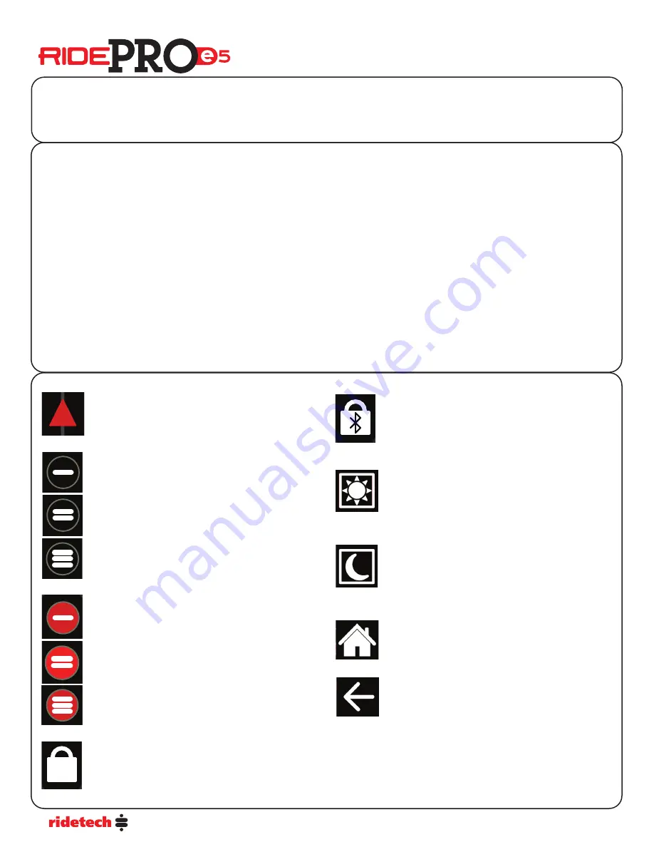
!

This icon is displayed on the main screen when the system 
sees an error.  You can see what errors you have by going 
to “Errors” in the main menu.

PRESET POSITION ICON

These icons are displayed on the main screen when the 
system is at a preset height.  It will be either position 1, 2, 
or 3.   If no icon is displayed, the system is not at a preset 
height.

GOING TO PRESET POSITION ICON

These icons are displayed on the main screen when the 
system is going to a preset height.  It will be either position 
1, 2, or 3.   You can cancel out of “going to preset” by 
selecting the “X” on the screen.

DISPLAY LOCKED ICON

This icon is displayed on the main screen when the display 
is locked.  The lock mode can me deactivated by pushing 
the “Menu” button.  The display will automatically lock 
after no buttons have been pushed for 30 seconds.

ERROR ICON

DISPLAY LOCKED - BLUETOOTH IN USE ICON

This icon is displayed on the main screen when the system 
is connected to a phone using the app.  This prevents the 
system from being controlled from the display while it is 
being controlled with a phone.  Closing the app will un-
lock the Bluetooth lock.

DISPLAY DAY TIME MODE ICON

This icon is displayed on the main screen when the system 
is in “Night Mode”.    Touching the icon will put the display 
in day time mode.  When the display is in night mode, it 
will be dimmer.  The brightness of the display in night 
mode can be adjusted in the main menu.

DISPLAY DAY TIME MODE ICON

DISPLAY NIGHT TIME MODE ICON

This icon is displayed on the main screen when the system 
is in “DAY Mode”.    Touching the icon will put the display in 
night time mode.  When the display is in day mode, it will 
be brighter.  The brightness of the display in day mode can 
be adjusted in the main menu.

HOME 

This icon is displayed on the menu screen when in the sys-
tem menu. Touching the icon will return you to the main 
control screen.

BACK 

This icon is displayed on the menu screen when in any 
selection from the main menu. Touching the icon will 
return you to the main menu screen.

Содержание RidePROe5

Страница 1: ...s 17 Error Codes and Text 18 19 Plumbing Diagrams 20 Wiring Diagrams back cover Contents Thank you for choosing a Ridetech air suspension control system We are committed to providing the best experience possible throughout the process of getting your car on air Our commitment doesn t end with your purchase in fact it has only begun This guide should provide you with the information you need to pro...

Страница 2: ...he tank pressure sensor Mounting the RidePro Air Valves The valves like the compressor are sealed and can be mounted in the same locations Although if the vehicle will be exposed to freezing temperatures it is a good idea to mount them in the engine bay if possible to reduce the possibility of freezing They can be mounted in any position Attach the ground strap to a good clean ground preferably th...

Страница 3: ...volt Grey Wire Primary Compressor Ground Blue Wire Secondary Compressor Ground OPTIONAL Mounting the Air Pressure Sensors These sensors are voltage based and do not need to be grounded Use thread sealant when installing pressure sensors in valve block Sensors can not be pointed down debris can collect and cause false readings The ECU is water proof and may be mounted in the engine bay or under the...

Страница 4: ...the corresponding corner Press a Yellow down arrow button to deflate the corresponding corner Multiple buttons can be pressed simultaneously on the Display or Mobile APP Inflate and deflate buttons can be pressed simultaneously PRESETS There are three user configurable Presets The Presets can be saved to whatever vehicle height you wish Typically Preset 1 is deflated vehicle height Preset 2 is Rid...

Страница 5: ... shorten the sensor arm and drill a new hole to ensure the arm is rotating enough during suspension travel to accurately determine vehicle height The sensor arm can also be removed from the sensor and clocked in four different positions It may also be necessary to bend the sensor arm and or linkage to achieve proper clearance and alignment The sensor will be mounted to the frame using self tapping...

Страница 6: ...e end with the end link 4 Push the end of the linkage into the end link The linkage doesn t require anything to hold it into the end link 5 Once both sides of the linkage have been finished secure the linkage to the sensor and suspension 69 Camaro Front 58 64 Impala Front Triangulated 4 Link Rear Rear Trailing Arm C 10 Truck Rear Ride Height Sensors Assembly of the Sensor Link Rods Sensor Mounting...

Страница 7: ... manifolds CONNECT POWER HARNESS 1 Connect the red power wire directly to the battery Use included fuse within 18 of battery 3 Gallon 30 amp fuse 5 Gallon 40 amp fuse 2 Connect the yellow ignition wire to switched 12v Fuse Panel is the best location 3 Connect the black wire to chassis ground CONNECT RIDE HEIGHT SENSORS if equipped See Ride Height Sensor section for more information on installing a...

Страница 8: ...is not at a preset height GOING TO PRESET POSITION ICON These icons are displayed on the main screen when the system is going to a preset height It will be either position 1 2 or 3 You can cancel out of going to preset by selecting the X on the screen DISPLAY LOCKED ICON This icon is displayed on the main screen when the display is locked The lock mode can me deactivated by pushing the Menu button...

Страница 9: ...L NEED TO BE SWITCHED TO ON IF YOU ARE RUNNING 2 COMPRESSORS YOU MAY GET ERROR 143 BEFORE YOU TURN COMPRESSOR 2 ON IF YOU GET THIS ERROR GO TO THE SETUP MENU AND TURN COMPRESSOR 2 ON THE ERROR WILL CLEAR AFTER THE IGNITION IS CYCLED Compressor on PSI This allows one to select at what pressure the compressor will be turned on By default the system turns the compressor on when the tank pressure drop...

Страница 10: ...t Sensors it will automatically display level sensor voltage Control Panel Users Guide The Reset ECU screen allows you to clear the ECU and return it to the factory defaults The Reset ECU option has a 2 layer verification to prevent you from accidentally resetting the ECU It is necessary to select OK on each screen to reset the ECU If you select the OK two times all calibration and preset data is ...

Страница 11: ... the ignition is turned off then back on Dump Tank has a secondary screen to verify you want to dump the tank Control Panel Users Guide The Menu Diagnostics screen can be used to diagnose problems issues specifically with the level sensor positioning during installation and or the vehicle charging system Each corner can be manually inflated and deflated via the buttons surrounding the read out scr...

Страница 12: ...he display can be changed The orientation you select will be red on the screen Each icon shows the position of the preset buttons Touch the button that represents how you would like your display oriented All 4 choices are demonstrated with these images PRESET BUTTONS RIGHT Default Setting PRESET BUTTONS LEFT PRESET BUTTONS DOWN PRESET BUTTONS UP The Menu Info screen displays information about the ...

Страница 13: ...seconds P2 Set will pop up select OK If you are not running level sensors you will need to program all 3 presets The Menu Calibration screen allows the user to calibrate the system Though Calibration is not required for manual control of the system Calibration is required to enable functionality of the Presets During Calibration the system learns specific characteristics of the vehicle into which ...

Страница 14: ...he vehicle to your desired ride height and hold 2 for 5 seconds 12 Calibration complete select the OK Display will return to the Main Screen 13 Cycle the vehicle s power by turning off the key On an newer vehicle you may have to open the door to kill the power to the system Calibration PRESSURE AND HEIGHT CALIBRATION with Level Sensors Calibration ATTENTION The vehicle MUST be running in order to ...

Страница 15: ... caused by debris stuck on valve seat Inflate and deflate several times or disassemble valve Information about servicing the valves can be found at https www ridetech com tech solenoid valve service One air spring leaks up over a period of time Diagnosis A Inflate valves leaking Air seeps past inflate valve and into air spring Solution A Usually caused by debris stuck on valve seat Inflate and def...

Страница 16: ...ll not inflate or deflate but the others inflate and deflate Diagnosis A With the vehicle running check to see if the valve clicks when the button is pushed Solution A If no click check the harness going to valves and the grounds at the valve block Diagnosis B With the vehicle running check to see if the valve clicks when the button is pushed Solution B If no click check the grounds at the valve b...

Страница 17: ...backwards of each other If the zero reading moves to the left rear the sensor is bad or there is a problem in the wiring If you move the sensor wires and now the left rear has a reading there is probably no air in the right rear corner Check your valve air line and air spring for the right rear Tip You can also switch pressure sensors around to help determine if you have a bad sensor Make sure you...

Страница 18: ...VOLTAGE ERROR 82 LR POSITION HIGH VOLTAGE ERROR 92 RR POSITION HIGH VOLTAGE Wire harness damaged or sensor has failed ERROR 63 LF POSITION NO MOVEMENT ERROR 73 RF POSITION NO MOVEMENT ERROR 83 LR POSITION NO MOVEMENT ERROR 93 RR POSITION NO MOVEMENT Sensor improperly installed or has failed ERROR 64 LF POSITION WRONG LOCATION ERROR 74 RF POSITION WRONG LOCATION ERROR 84 LR POSITION WRONG LOCATION ...

Страница 19: ...harging system operating correctly ERROR 162 VEHICLE VOLTAGE HIGH Vehicle voltage has exceeded 18V Is the vehicle s engine running Is the vehicle s charging system operating correctly Is the vehicle on a battery charger ERROR 163 COMMUNICATION Is the display harness plugged into the ECU Is the display harness pinched or shorted ERROR 164 CALIBRATION FAIL Calibration failed due to errors during cal...

Страница 20: ...U LRU RFD LFD RFU LFU RRD LRD RRU LRU Single Compressor Systems Tank Tank Compressor Compressor Compressor Solenoid Valve Solenoid Valve Driver Front Driver Front Driver Rear Driver Rear Passenger Rear Passenger Rear Passenger Front Passenger Front Check Valve Check Valve ...

Страница 21: ...Grey Right Deflate Rear Valve Harness Blue Left Inflate Black Right Inflate Red Left Deflate Orange Right Deflate Front Valve Harness 20 Amp Fuse LR RR LF RF 20 Amp Fuse 15 Amp Fuse 30 Amp Fuse 30 Amp Fuse Ground Ground Blue LR Brown LF Orange RF Tan RR Wiring Diagram Shown with level sensor upgrade 350 S St Charles St Jasper IN 47546 812 481 4969 CUTTING OFF ANY OF THESE PLUGS WILL VOID THE WARRA...

Отзывы: