background image

3. Preventive Maintenance

PM Tables

There are no PM parts for this machine.

21

3

Содержание HL-F1

Страница 1: ...Model HL F1 Machine Code H558 Field Service Manual 14 May 2010...

Страница 2: ......

Страница 3: ...nplugged the telephone line cord first and then the power cord from the AC power outlet Do not handle the plug with wet hands Doing this might cause an electrical shock After you use the machine some...

Страница 4: ...s may cause a fire or electrical shock WARNING IMPORTANT SAFETY INSTRUCTIONS When using your telephone equipment basic safety precautions should always be followed to reduce the risk of fire electric...

Страница 5: ...lt in minor or moderate injury or damage to the machine or other property Obey these guidelines to avoid problems such as misfeeds damage to originals loss of valuable data and to prevent damage to th...

Страница 6: ...breviations This manual uses several symbols and abbreviations The meaning of those symbols and abbreviations are as follows See or Refer to Clip ring Screw Connector Clamp SEF Short Edge Feed LEF Lon...

Страница 7: ...7 2 Installation Installation Requirement 19 Choosing a Location 19 Fax Installation 19 3 Preventive Maintenance PM Tables 21 4 Replacement and Adjustment Transferring Received Fax Data 23 Operating P...

Страница 8: ...oltage PS PCB ASSY 76 Main PCB 78 PS PCB Unit Fan 40 79 Laser Unit 83 Sub Chute ASSY 85 Link Lever 86 Tail Edge Actuator 87 Regist Front Actuator Regist Front Spring 88 Regist Sensor PCB ASSY 89 Regis...

Страница 9: ...119 Requirement Adjustment after Parts Replacement 120 If You Replace the Main PCB 120 If You Replace the CIS 123 If You Replace the Laser Unit 123 5 Service Maintenance Entry into the Maintenance Mo...

Страница 10: ...147 Output of Transmission Log to the Telephone Line Function code 87 147 Cancellation of the Memory Security Mode 148 Firmware Installation 149 Installing the Update Data to the Machine 149 Setting...

Страница 11: ...n setting 4 187 WSW27 Function setting 5 188 WSW28 Function setting 6 189 WSW29 Function setting 7 190 WSW30 Function setting 8 190 WSW31 Function setting 9 190 WSW32 Function setting 10 191 WSW33 Fun...

Страница 12: ...02 WSW51 Function setting 16 202 6 Troubleshooting Error Indication 203 Troubleshooting Guide 204 Introduction 204 Precautions 204 Checking Prior to Troubleshooting 204 Paper Feeding Problems 205 Soft...

Страница 13: ...1 Product Information Specifications See Appendices for the Specifications 11 1...

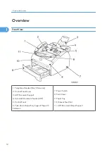
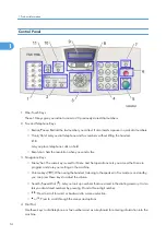
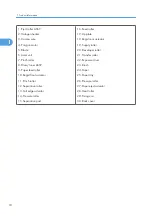
Страница 14: ...trol Panel Cover 3 ADF Document Support 4 Automatic Document Feeder ADF 5 Control Panel 6 Face down Output Tray Support Flap with Extension 7 Power Switch 8 Front Cover 9 Paper Tray 10 Manual Feed Slo...

Страница 15: ...Rear View 12 USB Interface Connector 13 Back Cover 14 AC Power Connector Overview 13 1...

Страница 16: ...d for Menu and Set operations Lets you access the Menu to program and store your settings in the machine Volume keys When using the handset listening to the speaker in Fax mode or on standby you can p...

Страница 17: ...ification Report Help List Quick Dial List Fax Journal and User Settings 8 Mode Keys Fax Lets you access Fax mode Copy Lets you access Copy mode 9 Liquid Crystal Display LCD Displays messages on the s...

Страница 18: ...Components The equipment consists of the following major components 1 Product Information 16 1...

Страница 19: ...r Chute Cover ASSY 7 Laser Unit 8 Side Cover R 9 PS PCB Unit 10 Frame Unit 11 Front Cover 12 Paper Tray 13 High voltage PS PCB 14 Side Cover L 15 Main PCB 16 Fixing Unit 17 Rear Chute Cover 18 Back Co...

Страница 20: ...11 Pinch roller 12 Separation roller 13 Tail edge actuator 14 Pressure roller 15 Separation pad 16 Feed roller 17 Up plate 18 Regist rear actuator 19 Supply roller 20 Developer roller 21 Transfer roll...

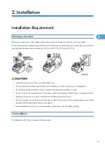
Страница 21: ...ear heaters air conditioners water chemicals or refrigerators Do not expose the machine to direct sunlight excessive heat moisture or dust Do not connect your machine to an AC power outlet controlled...

Страница 22: ...2 Installation 20 2...

Страница 23: ...3 Preventive Maintenance PM Tables There are no PM parts for this machine 21 3...

Страница 24: ...3 Preventive Maintenance 22 3...

Страница 25: ...n this order to access user accessible functions of the maintenance mode The FAX TRANSFER appears on the LCD 4 To check the number of received files press the 1 key The 1 NO OF JOBS appears on the LCD...

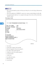
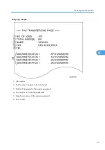
Страница 26: ...l be attached A cover page and end page as shown below will be automatically attached instead Cover page sample 1 Job number 2 Total number of pages to be transferred 3 Station ID registered in the se...

Страница 27: ...mber 2 Total number of pages to be transferred 3 Station ID registered in the sender equipment 4 Fax number of the sender equipment 5 Telephone number of the sender equipment 6 Error codes Transferrin...

Страница 28: ...grounding wrist band and perform the job on a static mat Also take care not to touch the conductor sections on the flat cables or on the wire harness 6 Be sure to reinsert self tapping screws correct...

Страница 29: ...ver stopper Taptite bind B M4x12 1 0 79 0 1 8 1 Inner chute Taptite bind B M4x12 2 0 79 0 1 8 1 LV shield plate cover Screw pan s p washer M3 5x6 1 0 49 0 1 5 1 Top cover ASSY Taptite bind B M4x12 2 0...

Страница 30: ...2 Taptite cup S M3x6 2 2 0 78 0 1 8 1 0 69 0 1 7 1 CDCC PCB Screw Pan M3x6 2 0 49 0 1 5 1 Main PCB Taptite cup S M3x6 5 0 69 0 1 7 1 FG harness ASSY 1 Screw pan S P washer M3 5x6 1 0 59 0 1 6 1 LV shi...

Страница 31: ...que N m kgf cm Base plate Taptite bind B M4x12 3 0 78 0 1 8 1 Location of screw Screw type Q ty Tightening torque N m kgf cm Toner sensor PCB ASSY Taptite cup B M3x6 1 0 25 0 05 2 5 0 5 Location of sc...

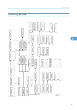
Страница 32: ...the Object Component On the next page is a disassembly flowchart which helps you access the object components To remove the fixing unit for example first find it on the flowchart and note its name Fix...

Страница 33: ...Disassembly Flowchart Before You Do 31 4...

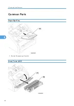
Страница 34: ...Common Parts Paper Eject Tray 1 Remove the paper eject tray A Drum Toner ASSY 4 Replacement and Adjustment 32 4...

Страница 35: ...ASSY B Paper Tray 1 Close the front cover A and pull out the paper tray B 2 Remove the paper from the paper tray 3 Remove the separation pad holder ASSY A and the separation pad spring B 4 Use a scre...

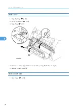
Страница 36: ...Tray p 32 2 Drum Toner ASSY p 32 3 Paper Tray p 33 4 Remove the section A of the back cover while opening the back cover slightly 5 Remove the back cover B Rear Chute Cover 1 Back Cover p 34 4 Replace...

Страница 37: ...2 Remove the rear chute cover A 3 Remove the paper eject actuator A and the eject actuator spring B Document Base ASSY 1 Paper Exit Tray p 32 2 Drum Toner ASSY p 32 3 Paper Tray p 33 Common Parts 35 4...

Страница 38: ...ove the two screws cup B M4x12 A to remove the document base ASSY B Side Cover L 1 Document Base ASSY p 35 2 Open the front cover A 3 Remove the side cover L B x 2 B M4x12 4 Replacement and Adjustment...

Страница 39: ...4 Disconnect the connector A of the speaker ASSY Handset Holder NA China only 1 Top Cover p 49 2 Open the panel unit A and remove the link stopper B Common Parts 37 4...

Страница 40: ...3 Release the four hooks to remove the handset holder A Speaker ASSY 1 Side Cover L p 36 2 Remove the speaker hold spring A and speaker ASSY B x 1 B M3x8 4 Replacement and Adjustment 38 4...

Страница 41: ...Side Cover R Link Stopper 1 Side Cover L p 36 2 Remove the side cover R A x 2 B M4x12 hooks 3 Remove the link stopper A from the top cover B Common Parts 39 4...

Страница 42: ...Panel Unit 1 Handset Holder p 37 2 Disconnect the panel harness A 3 Remove the panel unit B 4 Replacement and Adjustment 40 4...

Страница 43: ...4 Remove the separation rubber A ADF plate spring B and front plate spring C x 1 B M3x6 Common Parts 41 4...

Страница 44: ...5 Remove the actuator R A from the panel unit B 4 Replacement and Adjustment 42 4...

Страница 45: ...6 Release the four hooks to remove the panel rear cover A x 3 B M3x8 Common Parts 43 4...

Страница 46: ...he LCD harness A After disconnecting flat cable s check that each cable is not damaged at its end or short circuited When connecting flat cable s do not insert them at an angle After insertion check t...

Страница 47: ...9 Release the three hooks to remove the panel PCB ASSY A 10 Release the two hooks to remove the panel PCB ASSY A Common Parts 45 4...

Страница 48: ...11 Remove the rubber key A 4 Replacement and Adjustment 46 4...

Страница 49: ...12 Release the two hooks to remove the back light holder A 13 Remove the back light film A 14 Release the one hook to remove the LCD B Hook PCB ASSY 1 Handset Holder p 37 Common Parts 47 4...

Страница 50: ...2 Disconnect the connector A of the hook PCB ASSY B 3 Release the one hook to remove the hook PCB ASSY B 4 Remove the actuator hook A from the hook PCB ASSY B 4 Replacement and Adjustment 48 4...

Страница 51: ...Top Cover 1 Rear Chute Cover p 34 2 Remove the rear cover stopper A x 1 B M4x12 Common Parts 49 4...

Страница 52: ...4x12 spring x 1 Re assemble the inner chute A while pushing onto the pinch roller B of the inner chute with the eject roller C of the top cover D 4 Disconnect the three connectors from the main PCB A...

Страница 53: ...G harness ASSY A x 1 pan S P washer M3 5x6 6 Disconnect the connector A of the battery 7 Release the one hook to remove the battery B There is a danger of explosion if the battery is incorrectly repla...

Страница 54: ...t disassemble recharge or dispose of in fire Used battery should be disposed of according to local regulations 8 Disconnect the battery harness from the main PCB C 9 Release the six hooks to remove th...

Страница 55: ...10 Remove the paper eject roller ASSY A from the top cover B When removing the paper eject roller ASSY the spacer may come off easily Be sure not to lose it Common Parts 53 4...

Страница 56: ...11 Remove the LF ground plate A x 1 S M3x6 12 Release the two hooks to remove the bushing 5 A 4 Replacement and Adjustment 54 4...

Страница 57: ...13 Remove the document ejection roller ASSY B 14 Release the hook to remove the pressure roller ASSY A 15 Remove the two pressure rollers A from the pressure roller shaft B Common Parts 55 4...

Страница 58: ...16 Remove the LF spring A from the top cover B 17 Release the two hooks to remove the bushing 5 A 18 Remove the LF roller B 4 Replacement and Adjustment 56 4...

Страница 59: ...scanning drive LF FG harness ASSY A x 1 B M3x4 20 Remove the four bind taptite screws 21 Release the four hooks to remove the document chute ASSY A from the inner chute cover ASSY B x 1 B M4x12 Commo...

Страница 60: ...22 Remove the CIS A 23 Disconnect the CIS harness A 4 Replacement and Adjustment 58 4...

Страница 61: ...24 Remove the two CIS springs A 25 Remove the LF roller gear A Common Parts 59 4...

Страница 62: ...26 Remove the separation roller A 27 Remove the scanning driver ASSY A x 2 B M3x8 4 Replacement and Adjustment 60 4...

Страница 63: ...28 Remove the scanning motor F sub ASSY A x 1 M3x6 Common Parts 61 4...

Страница 64: ...Main Body NCU PCB ASSY 1 Paper Eject Roller ASSY p 49 Top Cover 2 Remove the NCU FG harness ASSY A x 1 pan S P washer M3 5x6 4 Replacement and Adjustment 62 4...

Страница 65: ...3 Remove the scanning drive LF FG harness A and NCU unit B x 2 B M4x12 4 Turn the NCU unit upside down 5 Remove the NCU PCB ASSY A x 2 S M3x6 6 Disconnect the NCU harness ASSY B Main Body 63 4...

Страница 66: ...Stopper L S 1 Remove the paper stopper ASSY A from the inner chute cover ASSY B 2 Remove the paper stopper S A from the paper stopper L B Front Cover 1 Paper Exit Tray p 32 4 Replacement and Adjustmen...

Страница 67: ...lease the hook A of the drive release cam from the front cover ASSY B 5 Release the hook A on the front cover ASSY from the chute B 6 Slide the front cover ASSY to the direction of the arrow shown in...

Страница 68: ...2 Turn the printer upside down Printer top side A 3 Remove the chute base B x 6 B M4x12 When re assembling the chute base check that the screws C are secured correctly For details see How to check des...

Страница 69: ...4 Remove the spring extension P R A from the gear 52 P R B 5 Release the hook and remove the gear 52 P R B Main Body 67 4...

Страница 70: ...ove the bush F R A 7 Remove the F R roller shaft ASSY B 8 Remove the link lever A from the hook of the pickup roller holder ASSY B 9 Remove the pickup roller holder ASSY B 4 Replacement and Adjustment...

Страница 71: ...roller holder ASSY B Be careful not to lose the spring A How to check Check that the distance A between the floor B and the separation roller collar C of the pickup roller holder ASSY is 45 5 to 47 5m...

Страница 72: ...an 47 5 mm which is not contacted with the roller is NOT acceptable F height 45 5 mm which is not contacted with the roller H less than 45 5 mm which is contacted with the roller is NOT acceptable Fix...

Страница 73: ...2 Disconnect the heater harness connector A and thermistor harness connector B 3 Remove the fixing unit C x 2 B M4x12 Be sure not to touch the pressure roller Main Body 71 4...

Страница 74: ...springs A 5 Remove the pressure roller ASSY pressure roller B PR arm ASSY C PR bush from the fuser frame D 6 Remove the two PR arm ASSYs A and two PR bushes B from the pressure roller C 4 Replacement...

Страница 75: ...from the fuser frame B and remove the four separate claw ASSYs C Align the separate claw ASSY with the shape of the fuser frame to remove Be careful not to damage the heat roller D when removing the...

Страница 76: ...eat roller A x 2 pan S P washer M3x8 9 Remove the halogen heater B When re assembling the heat roller A assemble the HR bush B onto the fuser frame C referring to the figure above 4 Replacement and Ad...

Страница 77: ...er A onto the fuser frame B so that the terminal of the heater harness C is at the top and secure the screws in the order shown in the figure above 10 Remove the HR gear A 11 Remove the two HR bushes...

Страница 78: ...e thermistor ASSY B x 1 B M3x12 When re assembling the thermistor ASSY A to the fuser frame B ensure the direction of the thermistor ASSY A is correct referring to the figure above High Voltage PS PCB...

Страница 79: ...PCB After disconnecting flat cable s check that each cable is not damaged at its end or short circuited When connecting flat cable s do not insert them at an angle After insertion check that the cabl...

Страница 80: ...rom the main PCB A After disconnecting flat cable s check that each cable is not damaged at its end or short circuited When connecting flat cable s do not insert them at an angle After insertion check...

Страница 81: ...d Updating of Settings Required After Parts Replacement After disconnecting flat cable s check that each cable is not damaged at its end or short circuited When connecting flat cable s do not insert t...

Страница 82: ...the duct film A 3 Remove the FG harness ASSY 1 B x 1 pan S P washer M3 5x6 4 Remove the LV shield plate cover A from the main frame R B x 2 S M3x6 x 1 pan S P washer M3 5x6 4 Replacement and Adjustme...

Страница 83: ...nsulation sheet A 6 Remove the ground wire A x 1 pan S P washer M3 5x6 7 Remove the AC holder B x 1 B M4x12 8 Remove the two bind B M4x12 taptite screws and then remove the LV shield plate C x 2 B M4x...

Страница 84: ...to the terminal is downwards 9 Remove the two cup S M3x6 taptite screws 10 Disconnect the four connectors from the PS PCB unit A and then remove the PS PCB unit A 11 Remove the power supply switch B f...

Страница 85: ...nit ASSY connector B first lift up the PS PCB unit C from the LV shield plate and disconnect the two connectors of the main PCB D and fan 40 E 12 Remove the Fan 40 A When re assembling the fan 40 unit...

Страница 86: ...2 Remove the FG harness ASSY 6 A x 1 S M3x6 3 Remove the laser unit B x 4 S M3x6 4 Remove the filter ASSY A from the air duct B 5 Remove the air duct B x 1 S M3x6 4 Replacement and Adjustment 84 4...

Страница 87: ...ode label A attached on the gear plate calking ASSY B with a new one supplied with a new unit C 2 to 3 mm D 1 to 2 mm Another barcode label supplied with a new unit is spare Make sure to throw it out...

Страница 88: ...2 Remove the sub chute ASSY A x 2 B M4x12 Link Lever 1 Pickup Roller Holder ASSY p 66 4 Replacement and Adjustment 86 4...

Страница 89: ...de 3 Pull the section B outwards and remove the link lever C When re assembling the link lever A insert the end of the link lever A into the main frame L B referring to the figure above Tail Edge Actu...

Страница 90: ...tuator A with the tail edge spring B 3 Remove the tail edge spring B from the tail edge actuator C Printer top side Regist Front Actuator Regist Front Spring 1 Pickup Roller Holder ASSY p 66 4 Replace...

Страница 91: ...front actuator A with the regist front spring B 3 Remove the regist front spring B from the regist front actuator C Printer top side Regist Sensor PCB ASSY 1 Regist Front Actuator Regist Front Spring...

Страница 92: ...ase the harness from the hook and remove the regist sensor PCB ASSY A x 1 B M3x6 B Printer top side Regist Rear Actuator Regist Rear Spring 1 Pickup Roller Holder ASSY p 66 4 Replacement and Adjustmen...

Страница 93: ...2 Remove the regist rear spring A 3 Remove the regist rear actuator B C Printer top side Fan Motor 60 Unit 1 PS PCB Unit Fan 40 p 79 Main Body 91 4...

Страница 94: ...2 Remove the three bind B M4x12 taptite screws and three FG harness ASSY 1 A 4 B 5 C x 1 each B M4x12 3 Remove the base plate D E Printer top side 4 Replacement and Adjustment 92 4...

Страница 95: ...ook and then remove the fan motor 60 unit A from the main frame R B When re assembling the fan motor 60 unit A make sure to turn the side with a label C outwards Toner LED PCB ASSY LED Holder 1 Fan Mo...

Страница 96: ...ove the toner LED PCB ASSY A from the main frame R B 3 Remove the LED holder C from the toner LED PCB ASSY D New Toner Actuator New Toner Actuator Spring 1 Laser Unit p 83 4 Replacement and Adjustment...

Страница 97: ...2 Remove the new toner actuator spring A 3 Release the hook and remove the new toner actuator B from the main frame L C New Toner Sensor Harness ASSY 1 High Voltage PS PCB ASSY p 76 Main Body 95 4...

Страница 98: ...remove the new toner sensor harness ASSY A from the main frame L B Cover Sensor 1 New Toner Sensor Harness ASSY p 95 2 Release the two hooks and remove the cover sensor A from the main frame L B 4 Rep...

Страница 99: ...Toner Sensor PCB ASSY 1 Cover Sensor p 96 2 Remove the toner sensor PCB ASSY A x 1 B M3x6 Main Motor ASSY 1 High Voltage PS PCB ASSY p 76 Main Body 97 4...

Страница 100: ...2 Remove the main PCB sheet A 3 Remove the FG harness ASSY 4 B and then remove the main shield plate C x 4 B M4x12 4 Replacement and Adjustment 98 4...

Страница 101: ...4 Remove the HVPS insulation sheet A 5 Remove the gear plate calking ASSY B x 3 B M4x12 Main Body 99 4...

Страница 102: ...6 Remove the main motor ASSY A x 3 S M3x6 Develop Joint 1 Main Motor ASSY p 97 2 Remove the develop joint A from the gear plate calking ASSY B 4 Replacement and Adjustment 100 4...

Страница 103: ...Solenoid ASSY 1 Main Motor ASSY p 97 2 Remove the P R solenoid ASSY A the P R solenoid lever B and the solenoid release spring P R C x 1 B M3x10 F R Solenoid ASSY 1 P R Solenoid ASSY p 101 Main Body 1...

Страница 104: ...2 Remove the gear ASSY A from the main frame L B The gear ASSY contains the small gears A Be careful not to lose them by disassembling the gear ASSY 4 Replacement and Adjustment 102 4...

Страница 105: ...3 Remove the F R solenoid ASSY A the F R solenoid lever B and the solenoid release spring F R C x 1 B M3x10 Main Frame L 1 New Toner Actuator New Toner Actuator Spring p 94 Main Body 103 4...

Страница 106: ...2 Remove the main frame L A x 2 B M4x12 Main Frame R 1 Main Frame L p 103 4 Replacement and Adjustment 104 4...

Страница 107: ...2 Remove the main frame R A x 3 B M4x12 Main Body 105 4...

Страница 108: ...Harness Routing Laser Unit 1 Main PCB 2 LD harness 5P 3 Adhesion tape 4 Laser unit 5 Polygon motor connector 4 Replacement and Adjustment 106 4...

Страница 109: ...FG harness ASSY 1 FG harness ASSY 2 FG harness ASSY 5 1 FG harness ASSY 2 2 FG harness ASSY 1 3 FG harness ASSY 5 4 FG harness ASSY 1 5 FG harness ASSY 5 6 Chute Harness Routing 107 4...

Страница 110: ...FG harness ASSY 1 Main PCB 2 FG harness ASSY 3 Laser unit 4 Replacement and Adjustment 108 4...

Страница 111: ...Regist sensor PCB ASSY 1 PS PCB unit 2 Regist sensor PCB ASSY 3 Chute Harness Routing 109 4...

Страница 112: ...Fan Motor 60 Unit 1 Fan motor 60 unit 2 Main PCB 4 Replacement and Adjustment 110 4...

Страница 113: ...Toner LED PCB ASSY Fan 40 1 Fan 40 2 Label side 3 Toner LED PCB ASSY 4 PS PCB unit Harness Routing 111 4...

Страница 114: ...Toner Sensor PCB ASSY 1 High voltage PS PCB ASSY 2 Toner sensor PCB ASSY 4 Replacement and Adjustment 112 4...

Страница 115: ...P R Solenoid ASSY F R Solenoid ASSY 1 High voltage PS PCB ASSY 2 F R solenoid ASSY 3 P R solenoid ASSY Harness Routing 113 4...

Страница 116: ...New Toner Sensor Harness Assy Cover Sensor 1 Main PCB ASSY 2 Harness guide 3 New toner sensor harness ASSY 4 Cover sensor 4 Replacement and Adjustment 114 4...

Страница 117: ...Panel Unit 1 Harness guide 2 Main PCB 3 Panel rear cover 4 Panel PCB 5 Panel cover 6 Panel PCB harness Harness Routing 115 4...

Страница 118: ...Hook PCB 1 Harness guide film 2 Hook PCB harness 3 Main PCB 4 Hook PCB 5 Harness guide film 4 Replacement and Adjustment 116 4...

Страница 119: ...Scanning Motor F Sub ASSY 1 Main PCB 2 Harness guide film 3 Scanning motor F sub ASSY 4 Scanning motor F sub ASSY 5 Harness guide film 6 Main PCB Harness Routing 117 4...

Страница 120: ...CIS 1 Main PCB 2 CIS 4 Replacement and Adjustment 118 4...

Страница 121: ...NCU PCB 1 Main PCB 2 NUC PCB 3 LF FG harness 4 Scanning driver ASSY 5 Document chute ASSY 6 NCU FG harness 7 LV shield unit Harness Routing 119 4...

Страница 122: ...Function code 74 Refer to p 144 EEPROM Customizing Function code 74 4 Check the control panel PCB for normal operation Function code 13 Refer to p 137 Operational Check of Control Panel PCB Function c...

Страница 123: ...nine digits of the machine and click the OK button Refer to the NOTE below for the serial number label A 5 The serial number is shown in the window and check if it is correct The setting of the serial...

Страница 124: ...ser unit serial label 3 Enter the last 4 digit numbers B of the machine 4 Then click the OK button Please refer to the illustration above for the identification and the location B of the laser unit se...

Страница 125: ...e the Laser Unit Inputting the adjusted value of the laser scanner 1 Double click the brmainte EXE file maintenance utility stored in the PC 2 Select Input Information from Menu 3 Select the applicabl...

Страница 126: ...de 8 Click the OK button Please refer to the illustration above for the identification and the location B of the laser unit serial label A The error of NG may be shown after the input of the adjusted...

Страница 127: ...List of Maintenance Mode Functions Section enter the corresponding 2 digit function code with the numerical keys on the control panel The details of each maintenance mode function are described in p 1...

Страница 128: ...ontrol Panel PCB p 137 16 Adjustment of Handset Volume p 138 32 Sensor Operational Check p 139 53 Received Data Transfer Function p 140 54 Fine Adjustment of Scan Start End Positions p 142 55 Acquisit...

Страница 129: ...The numbers in bold can be accessed by end users if the machine setting is changed For details see User Access to The Maintenance Mode on the next page List of Maintenance Mode Functions 127 5...

Страница 130: ...lded in the firmware switch tables in Appendix The service personnel should instruct end users to follow the procedure given below 1 Press the Menu Set A Start B and Menu Set A keys in this order For...

Страница 131: ...alized These will be initialized Remote activation code These will not be initialized Station ID data Outside line number Telephone function registration One touch dialing Speed dialing Group dialing...

Страница 132: ...n data This is because at the start of scanning operation the equipment initializes white and black level data and takes in the scanning compensation reference data 1 Press the 0 and 5 keys in this or...

Страница 133: ...m in and out displaying the current count on the LCD as shown below Current count 1st page in this example 3 To return the machine to the initial stage of the maintenance mode press the Stop Exit key...

Страница 134: ...using the control panel keys and buttons The firmware switches have been set at the factory in conformity to the communications standards and codes of each country Do not disturb them unless necessary...

Страница 135: ...WSW09 Protocol definition 1 WSW10 Protocol definition 2 WSW11 Busy tone setting WSW12 Signal detection condition setting WSW13 Modem setting WSW14 AUTO ANS facility setting WSW15 REDIAL facility setti...

Страница 136: ...ion setting 13 WSW36 Function setting 14 WSW37 Function setting 15 Firmware Switches WSW01 through WSW51 Continued WSW No Function WSW38 V 34 transmission settings WSW39 V 34 transmission speed WSW40...

Страница 137: ...lue to be set 0 or 1 using the 0 and 1 keys 5 Press the Menu Set key This operation saves the newly entered selector values onto the EEPROM and readies the machine for accepting a firmware switch numb...

Страница 138: ...CD 2 The machine prints out the configuration list as shown in the figure below 3 Upon completion of printing the machine returns to the initial stage of the maintenance mode Operation Check of LCD Fu...

Страница 139: ...a key or button is pressed Check that the displayed number is correct by referring to the illustration below If a key or button is pressed out of order the machine beeps and displays the INVALID OPERA...

Страница 140: ...e Start button The Low High 5B will appear on the LCD The above 5B indicates the setting value The value varies with setting condition 3 When press any one of the 1 3 4 or 6 key value will be changed...

Страница 141: ...STNKOFU which can be switched by pressing the Start key for machines Given below is the relationship between the LCD indication sensor names and sensor status LCD Sensors Sensing status DF Document fr...

Страница 142: ...re are both color and monochrome data in a file to be transferred the monochrome data will be transferred first If the receiver machine does not support the color function the sender machine cannot tr...

Страница 143: ...over page and end page as shown on the next page will be automatically attached instead Cover page sample 1 Job number 2 Total number of pages to be transferred 3 Station ID registered in the sender e...

Страница 144: ...5 Telephone number of the sender equipment 6 Error codes Fine Adjustment of Scan Start End Positions Function code 54 Function This function is to adjust the scan start end positions Operating Procedu...

Страница 145: ...nu Set key The ACCEPTED will appear on the LCD One second later the machine returns to the initial stage of the maintenance mode A 5 and 4 keys B Menu Set key C Stop Exit key The correlation between t...

Страница 146: ...ocedure 1 Press the 6 and 7 keys in this order in the initial stage of the maintenance mode The PAPER FEED TEST will appear on the LCD The test printing is started and the grid pattern is printed 2 To...

Страница 147: ...mation items appears on the LCD in the order given below 1 Jam count indicating how many times a paper jam has been occurred 2 Page count indicating how many pages the photosensitive drum has been pri...

Страница 148: ...counter COVERAGE Average black coverage TTL_PG Total number of pages printed COPY Number of copies made PC PRINT Number of PC prints made FAX Number of FAX outputs made TR1_PG Number of pages picked u...

Страница 149: ...of A4 size paper is calculated using video signals Machine Error Code Indication Function code 82 Function This function displays an error code of the last error on the LCD Operating Procedure 1 Press...

Страница 150: ...rt to receive the transmission log from the user s machine Cancellation of the Memory Security Mode Function This procedure can cancel the memory security mode Use this procedure if the user forgets h...

Страница 151: ...n your PC TopreventvirtualUSBdevicesfrombeingconfiguredlimitlessly usetheuniquedriverinstallationprocedure described below that enables your PC to identify terminals via a single virtual USB device On...

Страница 152: ...The window above appears 6 The screen above appears indicating the detection of new hardware device by the system And then click Next to proceed 5 Service Maintenance 150 5...

Страница 153: ...7 Select Search for a suitable driver for my device recommended and click Next Firmware Installation 151 5...

Страница 154: ...nd click Next 9 Select the folder where the copy of the BHL2 Maintenance Printer driver is located or click Browse to specify it then click OK This sample screen is captured on the Windows 2000 deskto...

Страница 155: ...10 Click Next Firmware Installation 153 5...

Страница 156: ...11 To proceed click Yes 5 Service Maintenance 154 5...

Страница 157: ...12 If the driver is successfully installed the following message window appears Click Finish to return to Windows Firmware Installation 155 5...

Страница 158: ...BHL2 Maintenance Printer icon is displayed Writing the update programs data onto the flash ROM of the machine After the installation procedure of the printer driver proceed to the firmware writing ope...

Страница 159: ...it When writing operation starts the machine beeps intermittently After approx 2 to 5 minutes the writing operation is complete and the machine automatically reboots and returns to the standby state 3...

Страница 160: ...nnected to a single PC via USB Please check the printer driver of the machine is installed in a host computer before working When not installed Please install a printer driver in a host computer befor...

Страница 161: ...you to customize the EEPROM according to language function settings and firmware switch settings Operating Procedure 1 Enter the Maintenance Mode The machine beeps for approx one second and displays M...

Страница 162: ...efer to WSW01 Dial pulse setting p 162 WSW02 Tone signal setting p 163 WSW03 PABX mode setting p 164 WSW04 TRANSFER facility setting p 165 WSW05 1st dial tone and busy tone detection p 166 WSW06 Redia...

Страница 163: ...9 WSW29 Function setting 7 p 190 WSW30 Function setting 8 p 190 WSW31 Function setting 9 p 190 WSW32 Function setting 10 p 191 WSW33 Function setting 11 p 192 WSW34 Function setting 12 p 192 WSW35 Fun...

Страница 164: ...9 End of copying beep and print in black p 201 WSW50 SDAA settings p 202 WSW51 Function setting 16 p 202 WSW01 Dial pulse setting Selector No Function Setting and Specifications 1 2 Dial pulse generat...

Страница 165: ...digit pause in pulse dialing Example If 1 2 and 3 are dialed when N is set by selectors 1 and 2 Selector 7 Switching between pulse DP and tone PB dialing by the function switch This selector determine...

Страница 166: ...and minimum pause B in tone dialing Example If 1 2 3 4 and 5 are dialed Selectors 5 through 8 Attenuator for pseudo ring backtone to the line These selectors are used to adjust the sound volume of a...

Страница 167: ...chine Upon detection of CNG signals by the number of cycles specified by these selectors the machine interprets CNG as an effective signal and then starts FAX reception Selector Cycle No 1 No 5 0 A 0...

Страница 168: ...WAIT 1 1 1 Detection Without WAIT 4 Max pause time allowable for remote ID code detection 0 2 seconds 1 1 second 5 6 Busy tone detection in automatic sending mode No 5 6 0 0 No detection 0 1 Detection...

Страница 169: ...or4issetto 0 2seconds forinstance onlyaremoteIDcodewhoseseconddigitisdetected within 2 seconds after detection of the first digit will become effective so as to activate the remote function Selectors...

Страница 170: ...ternational tone No 4 5 6 0 0 0 50 ms 0 0 1 210 ms 0 1 0 500 ms 0 1 1 800 ms 1 0 0 900 ms 1 0 1 1 5 sec 1 1 0 2 0 sec 1 1 1 2 5 sec 7 No of 2nd dial tone detection cycles 0 1 cycle 1 2 cycles 8 Allowa...

Страница 171: ...waitforthe2nddialtonetobesentviathecommunications line regardless of pulse dialing or tone dialing After that pressing the Redial Pause key will cause the machine to insert a WAIT of 3 5 seconds In t...

Страница 172: ...icable in those countries where no dial tone or line current detection is supported e g U S A Selectors 1 and 2 Dial tone frequency band control These selectors set the frequency band for the 1st dial...

Страница 173: ...tection level of 1st dial tone and busy tone before dialing No 6 7 8 0 0 0 21 dBm 0 0 1 24 dBm 0 1 0 27 dBm 0 1 1 30 dBm 1 0 0 33 dBm 1 0 1 36 dBm 1 1 0 39 dBm 1 1 1 42 dBm The WSW08 is not applicable...

Страница 174: ...40 sec 7 8 Timeoutforresponsefromthecalledstation in automatic sending mode No 7 8 0 0 55 sec in U S A and Canadian models 60 sec in other models 0 1 140 sec 1 0 90 sec 1 1 35 sec Selectors 1 through...

Страница 175: ...n automatic sending mode If the machine calling station receives no response no G3 command from the called terminal in automatic sending mode for the period specified by these selectors it disconnects...

Страница 176: ...training retries to be repeated before automatic fallback Selectors 7 and 8 Encoding system Compression This selector determines whether or not to allow the use of the MR MMR coding system WSW11 Busy...

Страница 177: ...00 ms 3 4 Max detection period for incoming calling signal CI being OFF No 3 4 0 0 6 sec 0 1 7 sec 1 0 9 sec 1 1 11 sec 5 6 Min detection period required for acknowledging incoming calling signal CI a...

Страница 178: ...be adjusted according to the user s line conditions Selectors 1 and 2 Cable equalizer These selectors are used to improve the pass band characteristics of analogue signals on a line Attenuation in th...

Страница 179: ...respectively regardless of whether selector 8 on WSW23 is set to 0 WSW14 AUTO ANS facility setting Selector No Function Setting and Specifications 1 2 Frequency band selection lower limit for incomin...

Страница 180: ...incoming calling signal CI These selectors are used to select the frequency band of CI for activating the AUTO ANS facility In the French models if the user sets the PBX to OFF from the control panel...

Страница 181: ...Selector 8 CRP option If a command error occurs in the machine calling station the machine usually waits for three seconds and then makes a retry three times This CRP option is a request command that...

Страница 182: ...W17 Function setting 2 Selector No Function Setting and Specifications 1 2 Off hook alarm No 1 2 0 0 No alarm 0 1 Always valid 1 X Valid except when call reservation is selected 3 4 Not used 5 Calenda...

Страница 183: ...transmission phases both at the calling and called stations Selectors 2 and 3 Detection enabled time for CNG and no tone After the line is connected via the external telephone or by picking up the han...

Страница 184: ...tors 1 through 3 the machine attempts to establish the transmission link via the MODEM If the establishment fails the machine automatically steps down to the next lowest speed andattemptstoestablishth...

Страница 185: ...ys has to fall back to 4800 bps transmission The setting made by this selector takes effect only when the Overseas Mode is set to ON Selectors 2 and 3 Overseas communications mode These selectors shou...

Страница 186: ...NG signal as long as the line is connected WSW21 TAD setting 1 Selector No Function Setting and Specifications 1 to 5 Not used 6 7 Not used 8 Erasure of message stored in the memory after the message...

Страница 187: ...any arbitrary point 2 3 Allowable training error rate No 2 3 0 0 0 0 1 0 5 1 0 1 1 1 2 4 5 Decoding error rate for transmission of RTN No 4 5 0 0 16 0 1 14 1 0 10 1 1 8 6 7 Not used 8 Limitation of at...

Страница 188: ...ponds with FTT Selectors 4 and 5 Decoding error rate for transmission of RTN The machine checks the actual decoding errors and then transmits an RTN according to the decoding error rate Number of line...

Страница 189: ...0 sec 1 0 1 12 sec 1 1 0 14 sec 1 1 1 16 sec 8 Not used Selectors 5 through 7 are applicable to the U S A models only Selectors 5 through 7 Pause between paging number and PIN These selectors set the...

Страница 190: ...cles to be detected when the line is connected via the external telephone except in the external TAD mode or via the built in telephone The machine interprets a CNG as an effective signal if it detect...

Страница 191: ...ive ringing pattern If this selector is set to 1 the machine detects only the number of rings if it is set to 0 the machine detects the number of rings and the ringing time length to compare the detec...

Страница 192: ...frequency signal These selectors are intended for the manufacturer who tests the machine for the Standard Never access them WSW29 Function setting 7 Not used WSW30 Function setting 8 Not used WSW31 Fu...

Страница 193: ...long rings e g short short long rings This selector sets the minimum ON and OFF duration of ringer signals that are required for the machine to interpret ringer signals as being ON or OFF This is to p...

Страница 194: ...d 8 Default contrast These selectors set the default contrast which applies when the machine is turned on or completes a transaction WSW33 Function setting 11 Selector No Function Setting and Specific...

Страница 195: ...xternal TAD operation If the machine receives this specified number of DTMF tone signals during external TAD operation it will not detect CNG afterwards If these selectors are set to 1 1 the CNG detec...

Страница 196: ...1 through 4 on WSW14 it starts the ringer sounding However the machine may fail to detect the CI signal normally due to noise superimposed at the time of reception To prevent it use selectors 6 throu...

Страница 197: ...fthesubsequentin memorymessagetransmission only when recording paper or toner runs out WSW38 V 34 transmission settings Selector No Function Setting and Specifications 1 2 Setting of the equalizer No...

Страница 198: ...ow much the modem steps down the transmission speed at fallback when called by the remote station If this selector is set to 1 the modem may step down the transmission speed from 33600 bps to 28800 bp...

Страница 199: ...speed for fallback These selectors are used to set the modem speed range With the first transmission speed choice specified by selectors 1 through 4 the machine attempts to establish the transmission...

Страница 200: ...etting made by selectors 1 through 4 on WSW39 If selector 3 is set to 1 to mask the 3429 symbols second when the first transmission speed choice is 33600 bps specified by selectors 1 through 4 of WSW3...

Страница 201: ...0 9600 12000 14400 16800 19200 21600 24000 28800 31200 33600 2800 4800 7200 9600 12000 14400 16800 19200 21600 24000 26400 3200 4800 7200 9600 12000 14400 16800 19200 21600 24000 26400 28800 31200 WSW...

Страница 202: ...e station is improper due to line loss This function applies to super G3 protocol signals WSW42 Internet mail settings Not used WSW43 Function setting 21 Selector No Function Setting and Specification...

Страница 203: ...unction Setting and Specifications 1 to 7 Not used 8 Switching between high speed USB and full speed USB 0 Auto switching between high speed USB ver 2 0 USB ver 1 1 and full speed USB ver 1 1 1 Fixed...

Страница 204: ...d flag the machine will wait for the command that should follow for the time length specified by these selectors WSW50 SDAA settings Not used WSW51 Function setting 16 Selector No Function Setting and...

Страница 205: ...promptly locate the cause of a problem if any the facsimile equipment incorporates the self diagnostic functions which display error messages for equipment errors and communications errors For detail...

Страница 206: ...ng with a circuit tester 2 When disconnecting the connectors do not pull the lead wires but hold the connector housings 3 Before handling the PCBs touch a metal portion of the machine to discharge sta...

Страница 207: ...cartridge is installed correctly Paper Feeding Problems Even if the paper is printed and ejected without any problems such as paper jams paper feeding problems below may appear Users can clear these...

Страница 208: ...it Is the pressure roller dirty Yes Clean the pressure roller No Replace the fixing unit F 3 Waves in the paper folds in the paper at the eject roller Possible cause and Remedy 1 Paper Is the problem...

Страница 209: ...o paper supplied as the cause of a malfunction see M 4 No paper supplied in Malfunctions in this Chapter F 6 Paper pickup Possible cause and Remedy 1 Disconnection of the pickup solenoid harness Is th...

Страница 210: ...port change it to a normal port 6 Try printing the test page 7 Try resetting the factory settings Possible cause and Remedy 1 Failure inside the printer Is it possible to print the test page No Ident...

Страница 211: ...this section check connectors for contact failure before measuring the voltage at the specified connector pins M 1 No AC power supplied Possible cause and Remedy 1 Supply voltage Is the correct voltag...

Страница 212: ...eck the connector the wiring from the connector and the DC load 3 Low voltage power supply PCB Refer to the chart 1 below No Replace the low voltage power supply PCB 1 Chart PCB lead pin lead pin Volt...

Страница 213: ...n pins 2 SOLENOID and 1 24V of the CN16 connector on the main PCB change from approx 24V DC to 0V within the specified time Yes Replace the HVPS No Replace the paper pickup clutch solenoid 4 Main PCB...

Страница 214: ...ixing unit and measure the resistance of the halogen heater lamp Is it open circuit Yes Replace the halogen heater lamp M 7 Laser Unit failure Possible cause and Remedy 1 Harness connection failure 1...

Страница 215: ...eared if leaving the printer power ON for ten minutes M 9 Main PCB failure Possible cause and Remedy 1 Main PCB Is it possible to print the test page with the method No Replace the main PCB 2 Software...

Страница 216: ...s held Yes Replace the switch 3 Main PCB failure Is the problem solved by replacing the main PCB Yes Replace the main PCB M 12 Maximum speed is slow Possible cause and Remedy 1 Two or more sheets of t...

Страница 217: ...ver turning the power ON and leaving the printer for ten minutes No Replace the thermistor M 14 The machine stops while idling Possible cause and Remedy 1 Front cover failure Is the cover opened by vi...

Страница 218: ...Image Defects 6 Troubleshooting 216 6...

Страница 219: ...r connection 2 Toner sensor failure toner cartridge side Is the problem solved when 4 or 5 pages are printed after the toner cartridge is replaced with a full one Yes The wiper of the toner cartridge...

Страница 220: ...h the wire cleaner 4 Try installing a new toner cartridge or drum unit Possible cause and Remedy 1 Corona failure contact failure Are the charge electrodes between the printer body and the drum unit d...

Страница 221: ...des at both sides 4 in p 240 Location of Grounding Contacts 2 Drum unit Are the drum shaft and drum electrode of the printer body connected correctly Yes Clean the shaft and the electrode 1 in p 240 L...

Страница 222: ...the problem solved after replacing the main PCB Yes Replace the main PCB 7 Laser unit failure Is the scanner interlock lever A damaged Is the scanner mirror broken or loose Yes Replace the laser unit...

Страница 223: ...PCB correctly No Connect the harness between the laser unit and the main PCB correctly 3 High voltage power supply PCB failure Is the problem solved after replacing the high voltage power supply PCB...

Страница 224: ...aper tray 2 Press the Menu Set Start keys in this order so that the machine goes into the maintenance mode 3 Press the 6 and 7 keys The machine starts to print the grid pattern continuously 4 When fiv...

Страница 225: ...rface scratched Yes Replace the drum unit 4 Cleaning failure Is the drum surface dirty with toner in streaks Yes Replace the drum unit 5 Scratch on the heat roller Is the surface of the heat roller sc...

Страница 226: ...roller intervals Yes After printing several pages the problem will disappear If not replace the toner cartridge 3 Scratch on the heat roller Are the horizontal stripes at 79mm heat roller intervals Ye...

Страница 227: ...idge may be damaged Install a new toner cartridge 3 Check the printer s environment High temperature and high humidity conditions can cause this problem 4 Damp wet paper might be used Try to change to...

Страница 228: ...d in the printer driver 3 The problem may disappear by itself Try printing multiple pages to clear this problem especially if the printer has not been used for a long time 4 The drum unit may be damag...

Страница 229: ...ng used No Recommend to use the specified types of paper Is the first printing position within 1mm of the tolerance specification Yes Adjust the Y offset by using the utility software supplied 3 Regis...

Страница 230: ...toner cartridge Yes 1 Toner is empty 2 The toner sensor is defective Clean the toner sensor 3 If the wiper in the toner cartridge is broken replace the toner cartridge with a new one 3 Fixing unit th...

Страница 231: ...re the unit correctly and tighten the screws 2 Scanner LD emission failure Scanner motor rotation failure Is the laser diode or the scanner motor defective No Replace the laser unit 3 Scanner connecti...

Страница 232: ...s the problem solved by replacing the laser unit Yes Replace the laser unit I 15 White spots User Check 1 If the problem is not solved after printing a few pages the drum unit may have glue from label...

Страница 233: ...paper might be used Recommend to change freshly unpacked paper 4 Environment Does the problem still appear after the printer has warmed up Yes 1 Replace the drum unit 2 Advise the user of the specifie...

Страница 234: ...rface of the exposure drum B 3 Wipe the surface of the exposure drum A with a cotton swab until the dust or paper powder on the surface comes off Do not wipe the surface of the exposure drum with some...

Страница 235: ...r to NOTE under the I 15 White spots 2 If the exposure drum is scratched or deteriorated exposed replace the drum unit 2 Drum connection failure Is the contact between the drum unit and printer body c...

Страница 236: ...r to its home position 2 in p 240 Location of Grounding Contacts 2 Corona dirty Is the corona wire dirty Yes 1 Clean the corona wire 2 If the problem still appears after cleaning replace the drum unit...

Страница 237: ...idge failure Is the problem solved after replacing the toner cartridge Yes Replace the toner cartridge 4 Drum unit failure Is the problem solved after replacing the drum unit Yes Replace the drum unit...

Страница 238: ...specified types of paper No Refer and compare with 4 under the Image defect I 15 I 20 Downward fogging of solid black Possible cause and Remedy 1 Toner cartridge failure Is the problem solved after r...

Страница 239: ...per tray connecting correctly No Clean the contacts 2 Drum unit Are the high voltage power supply and drum unit contacted correctly No Clean the contacts I 22 Light rain Possible cause and Remedy 1 Dr...

Страница 240: ...r specifications Damp paper thick media or rough surfaced paper can cause the problem 2 Check the printer s environment High temperature and high humidity conditions can cause the problem 3 Check that...

Страница 241: ...ower supply PCB I 24 Toner specks User Check 1 Check the paper used meets the recommended paper specifications A rough surfaced paper may cause the problem 2 The toner cartridge may be damaged Install...

Страница 242: ...Location of Grounding Contacts Drum unit A Toner cartridge B Drum unit 1 Exposure drum 2 Wire cleaner 3 Charge 4 Developer roller 5 Grid 6 Transfer roller 7 Cleaner 6 Troubleshooting 240 6...

Страница 243: ...e electrodes Incorrect Printout When the data is not printed correctly as it is seen on the PC screen follow the procedures below in the event of a specific error P 1 The printer prints unexpectedly o...

Страница 244: ...d section of this chapter P 2 Unable to print full pages of a document with the PRINT OVERRUN message User Check 1 Press the Start key on the control panel to print the data remaining in the printer 2...

Страница 245: ...ected to make sure the printer is set up correctly Remember that the printer emulates widely used printer selections HP Laser Jet 6P HP Laser Jet 6P Epson FX 850 IBM Proprinter XL Try setting the prin...

Страница 246: ...The control panel does not work User Check No point to be checked Possible and Remedy 1 Key sticking Any key on control panel is stuck Yes Clean up the panel cover or remove the burrs from panel cove...

Страница 247: ...escribed in p 131 Test Pattern Function code 09 No Check the symptom of the problem and refer to an appropriate section in this Chapter to solve the problem 2 Breakage of main PCB Printing can be made...

Страница 248: ...Replace the NCU PCB with anormal part 8 Control panel PCB Replacement of control panel PCB solves the problem Yes Replace the control panel PCB with a normal part 9 Main PCB Replacement of main PCB s...

Страница 249: ...ber key with a normal part 8 NCU PCB Replacement of NCU PCB solves the problem Yes Replace the NCU PCB with a normal part 9 Control panel PCB Replacement of control panel PCB solves the problem Yes Re...

Страница 250: ...onnection between main PCB and NCU PCB Main PCB and NCU PCB are properly connected No Fix the connection properly 6 Harness between main PCB and NCU PCB Harness is damaged Yes Replace the harness with...

Страница 251: ...connected No Fix the connection properly 6 Harness between main PCB and control panel PCB Harness is damaged Yes Replace the harness with a normal part 7 NCU PCB Replacement of NCU PCB solves the prob...

Страница 252: ...lacement of NCU PCB solves the problem Yes Replace the NCU PCB with a normal part 4 Main PCB Replacement of main PCB solves the problem Yes Replace the main PCB with a normal part 6 Troubleshooting 25...

Страница 253: ...when the timer is at the default settings If the timers are changed then the energy saved will be different For example if the timers are all set to 99 min the grey area will disappear and no energy i...

Страница 254: ...necessary to change the setting please try to make sure that the Sleep timer is not too long Try with a shorter setting first such as 30 min then go to a longer one such as 60 min if the customer is...

Страница 255: ...Model HL F1 Machine Code H558 Appendices 14 May 2010...

Страница 256: ......

Страница 257: ...cifications 3 General Specifications 3 Paper Specifications 4 Printable Area 6 Toner Cartridge Weight Information 8 Specifications List 9 2 Appendix Troubleshooting Guide Error Indication 19 Equipment...

Страница 258: ...2...

Страница 259: ...Liquid Crystal Display LCD 16 characters x 1 line Power Source 100 to 120V AC 50 60Hz 220 to 240V AC 50 60Hz Power Consumption Sleep 10W Standby 80W Peak 1100W Dimensions W x D x H 374 W x 374 D x 26...

Страница 260: ...lbs X O Thick paper or Thicker paper Transparency O Up to 10 sheets A4 or Letter O Transparency Label X O Thicker paper Envelop X O Envelope or Env Thick or Env Thin Card Stock X O Thick paper or Thic...

Страница 261: ...Xerox Premier 80 g m2 Xerox Business 80 g m2 Modo Paper DATACOPY 80 g m2 IGEPA X press 80 g m2 Xerox 4200DP 20lb Xerox 4024 28lb Hammermill Laser Paper 24lb Recycled paper Xerox Recycled Supreme Xero...

Страница 262: ...sheets be sure to fan the stack well Do not use organizer sheets that are stuck together The glue that is used might caused damaged to the printer When printing on the back of pre printed paper if the...

Страница 263: ...J K L M Folio 71 mm A4 A5 A6 B5 B6 DL C5 A4 Long 74 mm DL LEF 50 mm User Setting 3x5 C 50 mm All size of paper D 75 mm Letter Legal Executive Monarc Com 10 Organizer J K L M Folio 71 mm A4 A5 A6 B5 B...

Страница 264: ...Long 74 mm DL LEF 50 mm User Setting 3x5 C 50 mm All size of paper D 75 mm Letter Legal Executive Monarc Com 10 Organizer J K L M Folio 71 mm A4 A5 A6 B5 B6 DL C5 A4 Long 74 mm DL LEF 50 mm User Sett...

Страница 265: ...s 100 pages with 10g toner 5 coverage Specifications List GENERAL US Canada Europe Asia Pacific Print Engine Laser ALL CPU Speed SparcLite 96MHz Back up Clock Yes up to 4 days Operating Environment Te...

Страница 266: ...LCD Size 16 characters x 1 lines LCD Back Lit Yes 1 color On Screen Programming Yes Memory Capacity Standard MByte 16 Mbyte RAM Memory BackUp Yes up to 4 days Optional Memory N A Memory Security Yes...

Страница 267: ...opying 475W Power Consumption 10W 80W 1100W Power Save CPU Sleep N A Sleep Mode 00 99min Yes Energy Star Compliant N A Total Print pages Counter Internal LCD Print Yes Yes Yes Copy pages Counter Inter...

Страница 268: ...N A Monitoring the Line on Hold N A One Touch Dial 20 10 x 2 locations TELEPHONE US Canada Europe Asia Pacific Speed Dial 200 locations Figures of One Touch Speed Dial 20 digits Resisterable Number Of...

Страница 269: ...MH MR MMR JBIG Color FAX Document Send Receive N A Color FAX Memory Send Receive N A Fax Tel Switch Yes Super Fine Yes TX RX Gray Scale 64 Contrast Yes Auto Light Dark Smoothing N A Dual Access Yes E...

Страница 270: ...rt Standard Resolution JBIG US Canada Europe Asia Pacific ECM Error Correction Mode Yes Error Re Transmission Yes Broadcasting Yes 270 locations Manual Broadcasting Yes 50 locations Easy Receive Fax D...

Страница 271: ...ystem Setup User Setting List Yes INTERFACE External TAD Interface Yes Host Interface Serial N A Host Interface IEEE1284 N A Host Interface Full Speed USB2 0 Yes Ether Net 10 100base TX N A Cable incl...

Страница 272: ...B6 A6 EXE LTR LGL A4 B5 A5 B6 A6 EXE OS Windows 2000 XP Vista 7 Manual Feed Slot Custom Size 2 75x4 56 8 5x16 Envelope DL C5 CM10 Monarch Paper Type Plain Paper Recycled Paper Transparency Envelopes B...

Страница 273: ...Copy Sort Yes Reduction Enlargement 50 200 in 1 increments Resolution dpi 200 x 300 dpi Manual Duplex Copy N A N in 1 Yes Poster N A Image Enhancement N A Paper Type Media Setting Yes MESSAGE US Canad...

Страница 274: ...s 6 months after opening Temperature Normal condition 0 40 C Storage condition at a temperature of 40 to 50 C Up to 5 days Storage condition at a temperature of 20 to 0 C Up to 5 days Humidity Normal...

Страница 275: ...mation use maintenance mode function code 82 described in the List of Maintenance Mode Functions section of the Main Chapter that is make the equipment enter the maintenance mode and then press the 8...

Страница 276: ...ont cover of the machine Document Jam The document was not inserted or fed properly or the document scanned from ADF was too long Remove the document in the ADF ERROR MESSAGE CAUSE ACTION Data Remaini...

Страница 277: ...it for several minutes If the fan is not spinning you need to save the faxes before you follow the suggestions below Turn off the machine s power switch and then turn it on again If the error message...

Страница 278: ...e machine Remove the jammed paper Paper Jam Rear The paper is jammed in the back of the machine Remove the jammed paper Paper Jam Tray The paper is jammed in the paper tray of machine Remove the jamme...

Страница 279: ...se Solution 56 Eject sensor error The paper eject sensor actuator is being push down Thebackcoverisopened Close the back cover Paper eject sensor actuator caught on the surrounding parts Reassemble th...

Страница 280: ...defective Replace the new toner detection switch Main PCB defective Replace the main PCB 5C 69 Not used 6A Heater warming up timeout error Heater does not reach 60 C within 11 second Thermistor halog...

Страница 281: ...unit PS PCB unit defective Replace the PS PCB unit Main PCB defective Replace the main PCB 70 Not used 71 Polygon motor of laser scanner unit ASSY does not synchronize with the reference clock Laser...

Страница 282: ...ixing unit thermistor defective Short circuited Replace the fixing unit PS PCB unit defective Replace the PS PCB unit Main PCB defective Replace the main PCB 77 Fixing unit temperature goes up too hig...

Страница 283: ...Main PCB defective Replace the main PCB Main motor defective Replace the main motor 7B ASIC error on the main PCB Main PCB defective Replace the main PCB 7C Not used 7D Corona wire discharge Dust is a...

Страница 284: ...m The paper eject sensor actuator is being push down when turning the machine ON Paper is jammed Remove the jammed paper Paper eject sensor actuator caught on the surrounding parts Reassemble the pape...

Страница 285: ...ter ejecting paper Paper is jammed Remove the jammed paper Foreign materials in the paper path Remove foreign materials Paper ejection roller defective Replace the paper ejection roller Paper eject se...

Страница 286: ...lenoid defective Replace the F R solenoid Main motor defective Replace the main motor ASSY Main PCB defective Replace the main PCB 89 Recording paper jam in the manual slot The regist rear sensor actu...

Страница 287: ...emove the jammed document Actuator R caught on the surrounding parts Reassemble the actuator R Document rear sensor broken Replace the panel PCB ASSY Main PCB defective Replace the main PCB A3 The doc...

Страница 288: ...he CIS Main PCB defective Replace the main PCB AA AF Not used B0 CIS harness connection error CIS harness not connected properly Reconnect the CIS harness CIS defective Replace the CIS Main PCB defect...

Страница 289: ...emission intensity error of the LED array in document scanning Exceeding the upper limit CIS defective Replace the CIS Main PCB defective Replace the main PCB BA Gray level data error in document sca...

Страница 290: ...s which have not been stored are pressed Re store the dial numbers F2 Not used F3 F5 Internal software error Main PCB defective Replace the main PCB F4 Not used F6 PC interface error Main PCB defectiv...

Страница 291: ...the communications list 1 Calling Code 1 Code 2 Causes 10 08 Wrong number called 11 01 No dial tone detected before start of dialing 11 02 Busy tone detected before dialing 11 03 2nd dial tone not de...

Страница 292: ...minal not ready for polling 32 10 Remote terminal not equipped with password function or its password switch OFF 32 11 Remote terminal not equipped with or not ready for confidential mailbox function...

Страница 293: ...17 Invalid resolution selected 40 20 Invalid full color mode requested 5 Command reception checking the NSF and DIS after transmission of NSS and DCS Code 1 Code 2 Causes 50 01 Vertical resolution cap...

Страница 294: ...on except receiving into memory A0 13 Decoding error continued on 500 lines A0 14 Decoding error continued for 10 seconds A0 15 Time out 13 seconds or more for one line transmission A0 16 RTC not foun...

Страница 295: ...ent or document feed problem in ADF scanning in real time transmission Establishment of FAX communication FAX communication is established when the calling station receives a DIS reception capability...

Страница 296: ...2 Appendix Troubleshooting Guide 40 2...

Отзывы: