


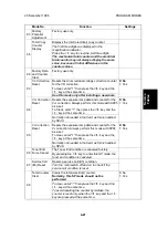
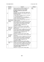


Mode No.
Function
Settings
8
Input Check
✝
Enter the desired number given in the following
table. The magnification indicator is used to display
the input data from the sensors while making a
normal copy.
Press the
key to perform this mode.
Component
No.
Sensor/
Switch/Signal
Reading
0
1
1
Registration Sensor
Paper Not
Present
Paper
Present
2
Exit Sensor
Paper Not
Present
Paper
Present
3
By-pass Feed
Paper End Sensor
Paper Not
Present
Paper
Present
4
Tray Paper End
Sensor
Paper
Present
Paper Not
Present
8
High Voltage Leak
Signal
No Leak
Signal
Leak Signal
Detected
9
Power Supply
Board Signal
120 V
230 V
10
Right Vertical
Guide Switch
Cover
Closed
Cover Open
12
Scanner HP Sensor
Sensor Not
Actuated
Sensor
Actuated
(HP)
13
4th/5th Mirror HP
Sensor
Sensor Not
Actuated
Sensor
Actuated
(HP)
14
Lens HP Sensor
Sensor Not
Actuated
Sensor
Actuated
(HP)
16
Sorter Paper Sensor
Paper Not
Detected
Paper
Detected
17
Sorter Wheel Switch
Switch
Actuated
(Switch
Pushed in:
Wheel
Moving)
Switch Not
Actuated
18
Sorter Bin HP
Switch
Switch Not
Actuated
Switch
Actuated
(HP)
19
Sorter Switch
Sorter
Closed
Sorter
Opened
20
ADF Installation
ADF Not
Installed
ADF
Installed
21
ADF Lift Switch
ADF Closed ADF Opened
22
Key Counter Set
Signal (Not Used)
Key Counter
Not Set
Key Counter
Set
Service
Tables
20 December 1996
PROGRAM MODES
4-11
Содержание FT 4015
Страница 2: ...SECTION 1 OVERALL MACHINE INFORMATION...
Страница 10: ...5 PAPER PATH 1 2 3 A219V502 wmf 1 By pass Feed 2 Paper Tray Feed 3 Copy Tray PAPER PATH 20 December 1996 1 8...
Страница 14: ...SECTION 2 DETAILED DESCRIPTIONS...
Страница 71: ...SECTION 3 INSTALLATION...
Страница 90: ...SECTION 4 SERVICE TABLES...
Страница 118: ...SECTION 5 PREVENTIVE MAINTENANCE...
Страница 126: ...SECTION 6 REPLACEMENT AND ADJUSTMENT...
Страница 190: ...SECTION 7 TROUBLESHOOTING...
Страница 212: ...Yes No Change or clean the defective parts Replace the main control board COPY QUALITY 20 December 1996 7 22...
Страница 222: ...SECTION 8 OPTIONS...
Страница 223: ...SECTION 9 APPENDIX TIMING CHART...
Страница 225: ...COPIER A219 ELECTRICAL COMPONENT LAYOUT 4 2 3 1 5 6 A219S500 wmf...
Страница 226: ...10 15 14 13 12 11 9 8 7 18 17 16 A219S501 wmf...
Страница 227: ...24 40 23 28 27 26 25 19 20 21 22 29 39 31 32 33 34 35 36 38 37 30 A219S502 wmf...


