Ricoh DDP 92 Скачать руководство пользователя страница 113

Appendix 10

II

L

00

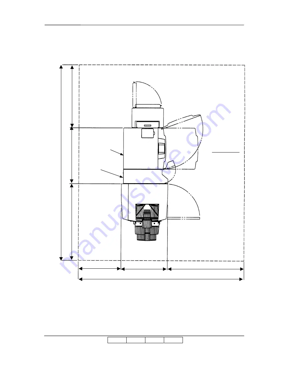
Appendix 1.10  Installation/maintenance area of the Printer, High Capacity Hopper, Transit Pass

Unit Type DDP and Finisher SR5000.

1000

(889)

3104

1215

2600

1200

(728)

672

Printe

r

Fin

ishe

r SR

500

0

T

ran

sit P

a

ss U

n

it

Ty

p

e

 D

D

P

(Unit : mm)

Operator Side

Area for Maintenance work

High

 Ca

p

a

city H

opp

e

r

Содержание DDP 92

Страница 1: ...Installation Manual 2005 Ricoh Printing Systems Ltd March 2007 N904117...

Страница 2: ......

Страница 3: ...4 02 2 5 02 2 15 01 3 2 01 3 6 01 4 7 01 4 18 01 4 27 01 4 28 01 Mar 17 06 03 2 4 03 2 5 03 Mar 5 07 04 5 8 00 Jan 22 08 05 Table of Contents i 01 ii 02 1 1 01 1 2 01 4 1 01 4 2 01 4 32 01 Added pages...

Страница 4: ...rating the DDP92 laser printer NOTICE TO USER In an effort to meet the demands of a rapidly changing technology the manufacturer is continually developing new features and functions to meet your chang...

Страница 5: ...BLANK...

Страница 6: ...cking Procedures 2 7 2 2 3 Parts Check in theAccessory Box 2 8 2 3 UNPACKING OF THE HIGH CAPACITY HOPPER 2 9 2 3 1 Confirmation of Parts Quantities 2 9 2 3 2 Unpacking Procedures 2 9 2 4 UNPACKING OF...

Страница 7: ...LATION 4 1 4 1 INSTALLATION IN THE COMPOSITION OF THE PRINTERAND FINISHER FINISHER SR5000 4 1 4 2 INSTALLATION IN THE COMPOSITION WITH THE HIGH CAPACITY HOPPER 4 16 4 3 INSTALLATION IN THE COMPOSITION...

Страница 8: ...ates a hazardous situation which if not avoided will or can result in minor or moderate injury or serious damage of product CAUTION Indicates a potentially hazardous situation which if not avoided may...

Страница 9: ...tion 2 1 Page 2 1 Section 2 2 Page 2 6 Section 2 4 Page 2 11 Perform unpacking where there is no dust or water leaking Section 2 1 Page 2 1 Section 2 2 Page 2 6 Section 2 3 Page 2 9 Section 2 4 Page 2...

Страница 10: ...2 Page 2 6 Section 2 3 Page 2 9 Choose the location to place device where there is no condensation Section 2 1 Page 2 1 Section 2 2 Page 2 6 Section 2 3 Page 2 9 Section 2 4 Page 2 11 Choose the loca...

Страница 11: ...SVT UL Listed CSACertified in NorthAmerica Conformed to IEC 950 in Europe Section 4 1 Page 4 4 Use the Power Supply Cable which is approximately 50 mm longer for the FG The cable should be designed a...

Страница 12: ...ion area Appendix Printer Finisher Transit Pass Unit Type DDP Finisher SR5000 High Capacity Hopper Container Stacker 1 Container Stacker 2 1 1 X X 1 2 X X X 1 3 X X 1 4 X X X 1 5 X X X 1 6 X X X X 1 7...

Страница 13: ...bolts 4 Level Meter Installation the Container Stacker 1 5 Environmental Conditions Table 1 3 Environmental Conditions Items Value Temperature 10 32 C 50 89 6 F Humidity 20 80 RH Wet Bulb 26 C 78 8 F...

Страница 14: ...is well balanced on the arms of the lift Also put the packing cushion between device and forklift so device is not damaged 5 Observe the speed limit of 300 mm sec 1 08 km hr when moving device Do not...

Страница 15: ...e V Bands and remove the Cap 2 Remove the screws 3 Remove the Packing Accessory box Ramps Upper Packing 4 Remove the Box Corner Packing Ramp Box Packing Accessory Box Screw Upper Packing Corner Packin...

Страница 16: ...veling bolts Jack up the Engine by rotating the leveling bolts 6 Remove the Base Packing 7 Place all Casters in the same direction 8 Lower the Engine on the Under Tray and screw the leveling bolts in...

Страница 17: ...loper Bottle Toner Black User s Guide Installation Manual Wire Cleaning Tool Interlock Stopper Maintenance PanelAss y CD ROM Documentation Special Tool Cable Clamp Screws CD ROM S W Manual CD ROM Driv...

Страница 18: ...r 4 WIRE CLEANING TOOL 1 For Customer Engineer 5 INTERLOCK STOPPER 1 For Customer Engineer 6 TONER BLACK 1 For Customer 7 INSTALLATION MANUAL 1 For Customer Engineer 8 SOFTWARE LICENSE AGREEMENT 1 For...

Страница 19: ...alanced on the arms of the lift Also put the packing cushion between device and forklift so device is not damaged 5 Observe the speed limit of 300 mm sec 1 08 km hr when moving device Do not move devi...

Страница 20: ...ox 2 Remove the two Upper packing Accessory Box 3 Remove the Tape of Protection Bag and take down the Protection Bag 4 Carefully lift the Finisher by two persons and stand on Floor Main Fixed Plate 1...

Страница 21: ...Unpacking 2 8 II L 00 2 2 3 Parts Check in the Accessory Box Table 2 4 Parts list in theAccessory Box No Parts Name Qty Use 1 JOINT COVER F 1 2 JOINT COVER U 1 3 JOINT COVER R 1...

Страница 22: ...not move device on unleveled floor Do not tilt device 15 or more 4 Choose the location to place device where the slope is less than 15 Only left and right direction from view of operator s side 5 Choo...

Страница 23: ...Unpacking 2 10 II L 00 2 Remove the two Upper Packing Outside Packing 3 Remove the High Capacity Hopper...

Страница 24: ...device is well balanced on the arms of the lift Also put the packing cushion between device and forklift so device is not damaged 5 Observe the speed limit of 300 mm sec 1 08 km hr when moving device...

Страница 25: ...emove the shipping box P P band and four corner packing 4 Peeling off the adhesive tapes remove the plastic bag 5 Cut the tape for corner on pallet and push down the side of pallet to outside Cap Spac...

Страница 26: ...Adjustable Open End Wrench and raised the Container Stacker 7 Remove the four base packing 8 Turned the all casters in the same direction 9 Install the ramp to the bottom of an inclination board Ramp...

Страница 27: ...2 6 HOPPER SPACER 6 7 WOOD SPACER 4 8 SCREW 12 1 M3 x 8 2 pieces 2 M4 x 8 4 pieces 3 M4 x 12 6 pieces Note In the case of composition of that the Container Stacker 1 and 2 connect the Hopper Spacer an...

Страница 28: ...ts in the package Table 2 8 Components in the package Unit of Packing Quantity Cover Sheet Feeder 1 Accessory Box 1 2 5 2 Unpacking Procedures 1 Remove the Outside Box 2 Remove the two Upper packing A...

Страница 29: ...ory Box Table 2 9 Parts list in theAccessory Box No Name Shape Quantity 1 PI 108H P K 1 2 Pre sensor assay 1 3 Guide axis 1 4 Miniclamp 2 5 Locking wire saddle 5 6 Locking stopper 4 7 Nylon clamp 3 8...

Страница 30: ...s no condensation 2 6 1 Confirmation of Parts Quantities Table 2 9 Components in the package Unit of Packing Quantity Transit Pass Unit Type DDP 1 2 6 2 Confirmation of the Accessories Parts Table 2 1...

Страница 31: ...and two Upper Packing 3 Remove the Transit Pass Unit Type DDP Upper Packing Upper Packing Lower Packing Lower Packing Transit Pass Unit Type DDP Shipping box Plastic bag SB Cover Paper Guide Ground P...

Страница 32: ...more on device 3 Observe the speed limit of 300 mm sec 1 08 km hr when moving device 4 Choose the location to place device where there is no condensation 2 7 1 Confirmation of Parts Quantities Table 2...

Страница 33: ...reparation for Installation of the Printer 3 1 1 Removing the Protection Tape and Mat from the Engine 1 Remove the Tapes and Mats from the Engine 2 Open the Front Cover 3 Remove the Tapes and TH Packi...

Страница 34: ...pes and Mat 6 Turn the TH Handle counterclockwise to close the TH Unit 3 1 2 Set the PS Air Filter for the Engine Rear Cover 1 Take out the PSAir Filter from Accessory Box 2 Install the PSAir Filter t...

Страница 35: ...tallation 3 3 II L 00 3 1 3 Removing the Protection Tape from 2000 Sheet Hopper 3 1 4 Removing the Protection Tape from 500 Sheet Hopper 2 portion Tape 500 Sheet Hopper Tape 2000 Sheet Hopper 2000 She...

Страница 36: ...4 II L 00 3 2 Preparation for Installation of the Finisher 1 Unscrew the five screws to remove the Rear cover of the Finisher 2 Remove three lock materials from each guide plate 3 Remove two stacker...

Страница 37: ...Preparation for Installation 3 5 II L 00 4 Remove two lock materials inside the stacker on the side to be joined to the main body 5 Remove two lock materials inside the stacker lower...

Страница 38: ...r Truss screw M4x6 2 CAUTION When installing the Main tray fit the four auxiliary fittings to the guide holes of the Main tray before fixing screws 7 Install the paper exit tray lower on the lower up...

Страница 39: ...Preparation for Installation 3 7 II L 00 8 Install the Sub tray on the secondary exit portion then fix it with screws SEMS II M3x6 2 Sub tray...

Страница 40: ...r Installation of the High Capacity Hopper 1 Remove the Protection Tapes from the High Capacity Hopper 2 Remove the Paper 3 Remove the Protection Tape and Mirror Mat from the High Capacity Hopper Pape...

Страница 41: ...ws 2 Lift up the Paper Guide and move to the outside 3 Insert the upper and lower of the Paper Guide to a Guide hole for A4 At that time the Paper Guide is outside of the Size Guide Sensor 4 Fix the M...

Страница 42: ...Protection Tapes 3 Peel off the mat under the Basket Opening procedure of the Front Cover L 1 Open the front cover R 2 Push A section in the direction of the arrow with Philips screwdriver and open t...

Страница 43: ...Preparation for Installation 3 11 II L 00 3 5 Preparation for installation of the Transit Pass Unit Type DDP 1 Remove the Protection Tapes from the Transit Pass Unit Type DDP Tape Tape Tape...

Страница 44: ...he Printer in any place where it will be subjected to direct sunlight since it may cause adverse effects on performance of the Printer 1 Releasing the Rear Cover 1 Unscrew the six M4 Screws 2 Unhook t...

Страница 45: ...Installation 4 2 II L 00 FS 108H FS 108R 2 Install the Joint cover U Joint cover F and the Joint cover R and install the Main Fixed plate 1 II L 01...

Страница 46: ...Installation 4 3 II L 00 Finisher SR5000 with Transit Pass Unit Type DDP 3 Install the SB Cover Paper Guide to the Printer SB Cover Paper Guide M3x6 Screw...

Страница 47: ...the Terminal Block and chassis 3 Fasten the Power Supply Cable by the Cord Lock 1 The voltage is constantly in unless the machine is unplugged or Breaker Switch is turned off 2 Unplug the Power Supply...

Страница 48: ...Power cable rating Min AC 250V Min 15A Type SJT or SVT UL Listed CSACertified in NorthAmerica Conformed to IEC 950 in Europe 4 Use the Power Supply Cable which is approximately 50 mm longer for the F...

Страница 49: ...es upper and lower into the upper and lower holes on the Finisher as illustrated below then lock them by pushing the Finisher to the back CAUTION When installing the Finisher don t hit following A par...

Страница 50: ...om adjust it by the height of the front and rear casters on the paper exit side of the Finisher The jack of the printer is adjusted when the SB cover doesn t open and shut smoothly the printer is lowe...

Страница 51: ...ard through the cable clamps with other cables like following figure 3 Connect the Power Cable to the Relay Connector like following figure 4 Switch on No 8 of SW1 of on the Print Circuit Board of the...

Страница 52: ...he three M4 Screws 2 Unhook the lower hook of the Rear Cover and release the Rear Cover 3 Release the Rear Cover by lifting up and pulling forward 8 Install the Block Sponge to the Transit Pass Unit T...

Страница 53: ...rojections in the Gap M4x8 Screw M4x8 Screw Projection Projection Transit Pass Unit Type DDP Upper Paper Guide SB Cover Paper Guide Install it carefully so that Upper Paper Guide and SB Cover Paper Gu...

Страница 54: ...en adjust Transit Pass Unit Type DDP to an arrow direction CHECK SB Cover Lower Paper Guide Adjust arrow direction Transit Pass Unit Type DDP Open and close the Lower paper guide When Lower Paper Guid...

Страница 55: ...CP board as follows Connection 1 black 20pin connector big size J745 black 20pin connector small size J747 black 14pin connector J791 5 Connect theAC cable to the J236 on the Low Voltage Power Supply...

Страница 56: ...L V P S J236 connector white 2pin AC cable CEAC cable connector white 2pin Location of connection 2 Location of Disconnection 1 connection 1 and DIP SW CP board J745 J747 J791 connection 3 connection...

Страница 57: ...r Cover of the Printer and Transit Pass Unit Type DDP 13 Install the Ground Plate to the Transit Pass Unit Type DDP M4x8 Screw Ground Plate M4x8 Screw M4x8 Screw M4x8 Screw Rear Cover of the Transit P...

Страница 58: ...sher SR5000 to the Transit Pass Unit Type DDP 1 Refer to the Installation Procedure of the Finisher SR5000 2 Install the FC Cover to the front door on the Finisher SR5000 M4x8 Screw FC Cover Finisher...

Страница 59: ...II L 00 4 2 Installation in the composition with the High Capacity Hopper 1 Install components other than the High Capacity Hopper 2 Draw the 2000 Sheet Hopper of the Engine 3 Remove the two M4 screw...

Страница 60: ...he Engine 5 Connecting the High Capacity Hopper 1 Put the Positioning Pin in the holeAand slide the High Capacity Hopper in the arrow direction 2 Make sure that the Cable does not get caught between t...

Страница 61: ...ix M4 screws and Rear Cover 9 Switch on No 6 of SW1 on the CP P K of the Engine 10 Install the Rear Cover 11 Turn the leveling bolt 2 Places to make the bottom of the High Capacity Hopper parallel wit...

Страница 62: ...2000 Sheets Hopper and set the paper guide at the position of 8 5 paper size 2 Remove the M4 Screw and the 2000 Sheets Hopper 3 Turn the four leveling bolts until casters are floated 4 Adjust the hor...

Страница 63: ...l that the hair of the Electrostatic Eraser does not fall 8 Install the Guide plate L by using the two M3x8 Screws with washer 9 Install the Joint Bracket U and Joint Bracket L by using the two M4x8 S...

Страница 64: ...ix M4 Screws 2 Unhook the lower hook of the Rear Cover and release the Rear Cover 3 Release the Rear Cover by lifting up and pulling forward 11 Remove the six M4 screws and the Rear Cover of the Conta...

Страница 65: ...ay 13 In order to adjust the height of Container stacker turn 180 degrees each of four leveling bolts and satisfy the following conditions and bolt the screw of a temporary tight 1 When the Front cove...

Страница 66: ...the height of the Frame s upper part of Container stacker and the Guide plate U s upper part is the same 3 Put the Level Meter on two places of Container stacker is level Check the Gaps ofA B C D are...

Страница 67: ...en the L paper guide A of the Container Stacker make sure that the SB cover can be opened When not open re adjusts to implement the item 4 3 1 12 and to lift the Container Stacker CHECK CP P K Holder...

Страница 68: ...ntainer Stacker Connection 4 on the below figure Do not use the 4 pin white connector Disconnection 2 on the below figure 19 Disconnect the 4 pin white connector of the DC IF cable of the printer from...

Страница 69: ...Installation 4 26 II L 01 20 Turn on the No 5 and Turn off the No 2 and 8 of the SW1 mounted on the CPXXX P K of the Engine 21 Install the Rear Cover of the Engine and Container Stacker M4 screw...

Страница 70: ...surface by using the two M3 Screws Be careful that the hair of the Electrostatic Eraser does not fall 4 Install the Joint Bracket U and Joint Bracket L by using the two M4x8 Screws 5 Remove the six M...

Страница 71: ...cover R is shut and it looks into the space between Container stacker 2 and Container stacker 1 from a front side the height of the Frame s projection of Container stacker and the Guide plate U s proj...

Страница 72: ...r side the height of the Frame s upper part of Container stacker 1 and the Guide plate U s upper part is the same 3 Put the Level Mater on two places of Container stacker is level Check the Gaps of A...

Страница 73: ...te translucence of the Container Stacker 2 Connection 3 on the below figure 11 Mount the CST FG cable coming from the Container Stacker 1 on the frame of the Container Stacker 2 by using M4 screw Conn...

Страница 74: ...L 00 13 Install the Rear Covers of the Engine Container Stacker 1 and Container Stacker 2 Rear Cover of the Engine M4 screws M4 screws M4 screws Rear Cover of the Container Stacker 2 Rear Cover of the...

Страница 75: ...r F Joint Cover U and Joint Cover R to the Container Stacker 2 and install the two Main Fixed Plate 1 to the Joint Cover R 2 Remove the rear covers from the Engine Container Stacker 2 and Finisher Con...

Страница 76: ...per and lower holes on the Finisher as illustrated below then lock them by pushing the Finisher to the back CAUTION When installing the Finisher don t hit following A part to the Printer Confirm the S...

Страница 77: ...e bottom adjust it by the height of the front and rear casters on the paper exit side of the Finisher The jack of the printer is adjusted when the SB cover doesn t open and shut smoothly the printer i...

Страница 78: ...e 6 Turn on the No 5 and 8 and turn off the No 2 of the SW1 mounted on the CPXXX P K of the Engine Turn on the H of the SW1 mounted on the P K of the Finisher FS 108R RoHs Compliance Unit Note Put the...

Страница 79: ...Installation 4 36 II L 00 Finisher SR5000 with Transit Pass Unit Type DDP 8 Install the SB Cover Paper Guide to the Container Stacker SB Cover Paper Guide M3x6 Screw...

Страница 80: ...ook the lower hook of the Rear Cover and release the Rear Cover 3 Release the Rear Cover by lifting up and pulling forward 10 Install the Block Sponge to the Transit Pass Unit Type DDP 11 Open the Fro...

Страница 81: ...sit Pass Unit Type DDP by using the four M4x8 Screws M4x8 Screw M4x8 Screw Projection Projection Transit Pass Unit Type DDP Upper Paper Guide SB Cover Paper Guide Install it carefully so that Upper Pa...

Страница 82: ...Cover Open and close the Lower paper guide When Lower Paper Guide and SB Cover Paper Guide collide repair it by hand because SB Cover Paper Guide may transform it CHECK Lower Paper Guide SB Cover Pap...

Страница 83: ...r big size J681 5 Pass the one cable through the Hole of Printer and Container Stacker from Container Stacker to Printer Signal cable black 20pin black 14pin connector 6 Connect the Signal Cable to th...

Страница 84: ...Installation 4 41 II L 00 connection 4 connection 3 disconnection 1 connection1 connection 5 Location of connection 2 and DIP SW CP board J747 J791 SW2 SW1 connection 2 CP board...

Страница 85: ...Stacker and Transit Pass Unit Type DDP 15 Install the Ground Plate to the Transit Pass Unit Type DDP M4x8 Screw Ground Plate M4x8 Screw M4x8 Screw M4x8 Screw Rear Cover of the Transit Pass Unit Type...

Страница 86: ...sher SR5000 to the Transit Pass Unit Type DDP 1 Refer to the Installation Procedure of the Finisher SR5000 2 Install the FC Cover to the front door on the Finisher SR5000 M4x8 Screw FC Cover Finisher...

Страница 87: ...FS 108H FS 108HBM No RoHS Compliance Unit 1 Remove the Top cover from the Finisher 1 Open the Sub tray cover remove the fixing screws and then remove the Sub tray 2 Remove the Caps on the rear side of...

Страница 88: ...Installation 4 45 II L 00 4 Open the Front door then remove the two screws from the front side of the Top cover 2 Remove the Rear cover from the Finisher Truss screw M4x6 5...

Страница 89: ...or the Pre Sensor window Note Remove any remaining burrs after cutting off the parts 4 Install the accessories on the underside of the Top cover 1 Install two Pre sensors Tapping screw M3x8 2 2 Secure...

Страница 90: ...eet Feeder make sure to position it by pushing toward the Printer side Don t hit the terminal of motor to the plate edge 2 Push down the Driven gear of the Cover Sheet Feeder so as to engage it with t...

Страница 91: ...6 Arrange the wire bundle 1 Insert five locking wire saddles into the Finisher 2 Secure the bundle with three wire saddles on the top 3 Insert the two Miniclamps into the Finisher 4 Secure the gray wi...

Страница 92: ...nstall the Pl 108H P K 1 Lead the remaining two wires from the Cover Sheet Feeder through the hole on the back the Finisher 2 Connect the shorter CN to CN 51 on the FS 108H P K FS 108HBM P K 3 Insert...

Страница 93: ...N of the Pre SensorAssay 2 Set and tighten the two screws on the rear side of the Top cover and put the caps back on 3 Set and tighten the two screws on the front side of the Top cover 4 Set and tight...

Страница 94: ...Installation 4 51 II L 00 5 Install the Sub tray on the secondary exit portion then fix it with the two screws 9 Reinstall the Rear cover 10 Install the Guide axis...

Страница 95: ...eeder which the printer had memorized is different from one with cover sheet feeder reported from the finisher when the power supply injection after Cover Sheet Feeder attachment Confirm the connectio...

Страница 96: ...1 Check the print contamination 1 Adjust the size guide of tray 1 to theA4 size or the Letter size 2 Adjust the sensor plate of tray 1 toA4 or LTR 3 Place theA4 size paper or the Letter size paper int...

Страница 97: ...he size guide of tray 2 and tray 3 to the A4 size or the Letter size 5 Adjust the sensor plate of tray 2 and tray 3 to A4 or LTR 6 Place the A4 size paper or the Letter size paper into the tray 2 and...

Страница 98: ...n 8 Push the Printer switch in the information menu screen 9 Confirm that the paper size of the tray 1 2 3 is theA4 size or the Letter size in the information printer screen 10 Push button twice and r...

Страница 99: ...f the status reports 1 Push the Reports switch in the main menu screen 2 Push the Status switch in the reports menu screen 3 It is returned automatically to the main menu and the Status page is printe...

Страница 100: ...er tray 4 Confirm that there is no printing contamination when sampling print samples If contaminated print samples clean the contaminated parts or continuous printing 5 4 Confirmation of the stapling...

Страница 101: ...k switch and check the paper feeding position on the slit between paper guides The cheater is in the accessory box of the printer 4 Set a standard point in the sample tray and the frame of Container S...

Страница 102: ...Installation 5 7 II L 00 Top Cover Interlock switch Container Stacker 2 Measurement position slit between paper guides 15 20 Hopper Spacer 20 20 100 100 Hopper Spacer...

Страница 103: ...condition of the feeding paper and tip of entrance paper guide on container stacker when the container s de curler function selects Disable 4 Check contact condition of the feeding paper and tip of en...

Страница 104: ...Don t install the Server in the following place The position in which the Cover and the Tray cannot be opened Under the tray of the Finisher Front of exhaust fan Top of the Printer Appendix 1 1 Instal...

Страница 105: ...0 Appendix 1 2 Installation maintenance area of the Printer High Capacity Hopper and Finisher 2565 1000 650 1200 665 700 2850 1200 Unit mm Area for Maintenance work Finisher High Capacity Hopper Print...

Страница 106: ...Appendix 3 II L 00 Appendix 1 3 Installation maintenance area of the Printer and Container Stacker 1 including sample tray Unit mm...

Страница 107: ...Appendix 4 II L 00 Appendix 1 4 Installation maintenance area of the Printer High Capacity Hopper and Container Stacker 1 including sample tray 3270 700 700 622 671 2565...

Страница 108: ...Appendix 5 II L 00 Appendix 1 5 Installation maintenance area of the Printer Container Stacker 1 including sample tray and Container stacker 2 including through path unit Unit mm 3886 700 700 665 1200...

Страница 109: ...Appendix 6 II L 00 Appendix 1 6 Installation maintenance area of the Printer High Capacity Hopper Container Stacker 1 including sample tray and Container stacker 2 including through path unit Unit mm...

Страница 110: ...Appendix 7 II L 00 Appendix 1 7 Installation maintenance area of the Printer Container Stacker 2 including through path unit and Finisher Unit mm 3468 700 700 665 1200...

Страница 111: ...Appendix 8 II L 00 Appendix 1 8 Installation maintenance area of the Printer High Capacity Hopper Container Stacker 2 including through path unit and Finisher Unit mm...

Страница 112: ...9 Installation maintenance area of the Printer Transit Pass Unit Type DDP and Finisher SR5000 700 889 2804 1215 2600 1200 728 672 Printer Finisher SR5000 Transit Pass Unit Type DDP Unit mm Operator S...

Страница 113: ...enance area of the Printer High Capacity Hopper Transit Pass Unit Type DDP and Finisher SR5000 1000 889 3104 1215 2600 1200 728 672 Printer Finisher SR5000 Transit Pass Unit Type DDP Unit mm Operator...

Страница 114: ...of the Printer Container Stacker 2 including through path Transit Pass Unit Type DDP and Finisher SR5000 650 1157 3722 1215 2600 1200 728 672 Printer Finisher SR5000 Transit Pass Unit Type DDP Unit mm...

Страница 115: ...pacity Hopper Container Stacker 2 including through path Transit Pass Unit Type DDP and Finisher SR5000 650 1157 4022 1215 2600 1200 728 672 Printer Finisher SR5000 Transit Pass Unit Type DDP Unit mm...

Страница 116: ...ter of the Printer CAUTION Make sure that the ground under the floor where the Leveling Bolt is installed is reinforced by the stand or other If the ground is not reinforced because of the holes on th...

Страница 117: ...Appendix 14 II L 00 Appendix 2 2 Locations of the Leveling Bolt and Caster of the Finisher Appendix 2 3 Locations of the Leveling Bolt and Caster of the High Capacity Hopper Engine Finisher...

Страница 118: ...Appendix 15 II L 00 Appendix 2 4 Locations of the Leveling Bolt and Caster of the Container Stacker Leveling bolt Caster Operator s side Container Stacker...

Отзывы: