background image

4

Safety Instructions

          WARNING

● Precautions for safe servicing

● 

Always remove the power cord plug from the outlet before starting work.

   → Otherwise, you could get a shock or your hands/fingers could be injured.

●   

However, the plug must be left connected to the outlet when performing function checks (of   

individual motors, a given series of operations, or electrical circuits).

When motors are operated alone in function checks, interlocks are deactivated, so be aware   

of the conditions and positions of related equipment, and take great care not to put your 

hands or fingers into moving parts.

● 

Do not touch the rotating parts when operating the drum removal button and the paper  

    eject switch or while the machine is running.

    →   Otherwise, your hands/fingers could get caught and crushed between the drum and 

rollers.

● 

Working clothes

• Wear clothing that enables you to work safely.

Work clothing should be close-fitting.

          CAUTION

2. Cautions for maintenance, inspection and servicing

● 

Tools

• Use tools that are appropriate for the work.

1

2

3

4

5

6

7

8

10

HELP Mode

Others

Troubleshooting

Maintenance / Check

Standard / Adjustment

Mechanism

Description of the Operation

Introduction

Содержание ADF DF7010

Страница 1: ...ADF DF7010 Field Service Manual November 2017 ...

Страница 2: ......

Страница 3: ...or servicing the machine with insufficient knowledge about it could lead to unforeseen accidents It is not possible to anticipate and describe in a manual such as this every possible hazard that could arise in the course of repair and servicing Therefore besides observing the safety instructions marked in this manual and on the machine s labels service personnel should be safety conscious and take...

Страница 4: ... of major parts disassembly and reassembly procedures specifications and procedures for adjustment maintenance inspection and corrective action This information is current as of September 2015 and applies basically to the model ADF DF7010 From time to time parts are changed to improve quality performance or safety Note therefore that in some cases certain parts or machine structure aspects describ...

Страница 5: ...are Ambient temperature 10o C 35o C Ambient humidity 40 70 Optimum temperature and humidity 20o C 65 If the machine is installed near to faucets water heaters or humidifiers or in cool sunless parts of a building or in the vicinity of water sources the paper could absorb moisture and curl leading to misfeeds or poor image quality Avoid installing the machine in places with open flames or where ref...

Страница 6: ...tion checks interlocks are deactivated so be aware of the conditions and positions of related equipment and take great care not to put your hands or fingers into moving parts Do not touch the rotating parts when operating the drum removal button and the paper eject switch or while the machine is running Otherwise your hands fingers could get caught and crushed between the drum and rollers Working ...

Страница 7: ...1 2 3 4 5 6 7 8 10 HELP Mode Others Troubleshooting Maintenance Check Standard Adjustment Mechanism Description of the Operation Introduction ...

Страница 8: ...stment 1 Mechanical System 40 2 Electrical System 42 Maintenance Check 1 Guaranteed Periodical Maintenance Cycle 48 2 Cleaning and Oiling 48 3 Periodical Maintenance Check List 49 Troubleshooting 1 Troubleshooting Guide 52 2 Error Display 54 HELP Mode 1 HELP Mode List 56 2 Overview 57 3 HELP Mode Functions and Operation Procedures 58 Others 1 Electrical Parts Layout and Their Functions 68 2 Overal...

Страница 9: ...1 1 Specifications 8 2 Dimensions 9 3 Part Names 10 1 Machine Exteriors Paper infeed side 10 2 Cross Section Structure Surface 11 Introduction Chapter 1 ...

Страница 10: ...m Operating temperature 10 35 degrees C 50 95 degrees F Specifications are subject to change without prior notice due to continual improvements 1 The following types of document cannot be used Documents with large file binding holes Documents with staples or paper clips attached Documents with markedly curling ends sides or marked folds Documents with tears or rough edge Chemically treated documen...

Страница 11: ...1 9 Chapter 1 2 Dimensions 2 Dimensions Unit mm ...

Страница 12: ...10 Chapter 1 3 Part Names 3 Part Names 1 Machine Exteriors Paper infeed side 1 2 3 4 No Name 1 Document tray 2 ADF cover 3 ADF Rear cover 4 ADF Front cover ...

Страница 13: ... interlock 3 ADF document sensor 4 ADF feed roller 5 ADF clutch A 6 ADF paper separator unit 7 Feed roller A 8 ADF clutch B 9 ADF document jam sensor 10 ADF document size PCB UNIT 11 ADF document cover open close switch 12 ADF document cover open close switch 2 for interlock 13 ADF document lead edge sensor 14 Glass 15 Feed roller B 16 Ejection roller ...

Страница 14: ...MEMO ...

Страница 15: ...ment Detection 15 2 Basic Operation for Feeding Paper to Scanner 16 3 Operation on Continuous Master Making 17 3 Function of Parts and Circuit 18 1 Interlock Circuit 18 2 Document Sensors 19 3 ADF Stepping Motor ADF Clutch A B 20 4 ADF Cover Switch 21 5 ADF Document Cover Open Close Switch 22 ...

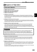
Страница 16: ...stepping motor Two clutches A and B are used to engage or disengage the ADF feed roller and the feed roller The clutch is turned on only for feeding paper to engage the scanner stepping motor with the driving system for the ADF feed roller After the document reaches the feed roller clutch A is turned off and clutch B is turned on The roller follows the movement of the document fed by the ejection ...

Страница 17: ...han the document reading speed to eject the document When the document is fed approx 20 mm after the reading is finished the ADF stepping motor stops IMPORTANT The reading of document is terminated at the earlier time when the longitudinal length is fed of the document size selected on the control panel or the document is fed approx 20 mm after the rear end is detected If master making for the doc...

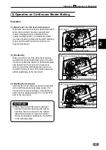
Страница 18: ...sitioning ADF Clutch A and the ADF stepping motor are turned off when the document is fed 16 mm after the ADF document jam sensor is photointerrupted This prevents the position of the documents from deviating which is caused by meandering during paper feeding If the front end of the document does not reach the ADF document lead edge sensor within 5 seconds after the ADF document jam sensor is phot...

Страница 19: ...d the ADF clutch A is turned on to feed the document 2 Positioning When the front end of the document reaches the ADF document lead edge sensor the ADF document lead edge sensor is photointerrupted and detects the front end of the document which turns off the ADF stepping motor and the ADF clutch A to hold This method assures stable positioning of the document 3 Reading the document After the fron...

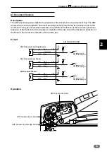
Страница 20: ... the ADF cover and ADF document cover are closed The unit stops immediately when the ADF cover or ADF document cover are opened during operation ADF Cover Switch2 When the ADF Cover is closed OPEN ADF Document Cover Switch 2 When the ADF Document Cover is closed OPEN White White White CN4 25 26 2 1 ADF DRIVE PCB UNIT CN4 1 2 24V DRIVE PCB UNIT Brown Blue 1 2 31 32 25 26 When the ADF Cover is opene...

Страница 21: ...ion of the front end of the document detection of the rear end of the document detection of the finish of the document detection of document jam ADF Document Lead Edge Sensor ADF Document Jam Sensor ADFDocument Sensor 3 2 1 1 2 3 1 2 3 5V GND 5V GND 5V GND Red Light green Blue CN2 1 2 3 CN2 4 5 6 CN2 7 8 9 Red Orange Blue Rad Yellow Blue ADF DRIVE PCB UNIT 5V 5V 5V 5V 5V 5V 5V 0 0 5V 5V 0 Photopas...

Страница 22: ...r The paper feed roller is engaged with the drive system when the ADF clutch A is turned on Also the feed roller A is engaged with the drive system when the ADF clutch B is turned on ADF Stepping Motor ADF Clutch A ADF Clutch B 3 1 4 6 Black Light green Pink Blue CN3 1 2 3 4 ADF DRIVR PCB UNIT CN3 5 6 CN3 7 8 Black Black White White 24V 24V 1 2 1 3 2 1 3 1 ...

Страница 23: ...R will be displayed ADF Cover Switch Yellow Yellow CN3 11 12 ADF DRIVEPCB UNIT When the ADF Cover is closed OPEN When the ADF Cover is opened CLOSE 5V 5V 0 When the ADF Cover is closed When the ADF Cover is opened ADF Cover Switch ON ADF Cover Switch OFF Operation When the ADF cover is closed the switch is pressed OPEN When the ADF cover is open the actuator is released the micro switch is turned ...

Страница 24: ... SCANNER COVER will be displayed ADF Document Cover Open Close Switch Green Green CN3 9 10 ADF DRIVE PCB UNIT When the ADF Document Cover is closed OPEN When the ADF Document Cover is opened CLOSE 5V 5V 0 ADF Document Cover Switch ON ADF Document Cover Switch OFF Operation When the ADF document cover is closed the switch is pressed OPEN When the ADF document cover is open the actuator is released ...

Страница 25: ... Cautions Regarding Disassembly and Assembly Chapter 3 1 Exterior 24 1 Removing the Document Tray 24 2 Removing the ADF 24 3 Removing the ADF Front Rear Cover 27 4 Removing the ADF Document Cover 27 5 Removing the ADF Unit 28 6 Removing the ADF Document Cover Open Close Switch 28 2 ADF Section 30 1 Removing the ADF Cover 30 2 Removing the ADF Document Sensor 30 3 Removing the ADF Feed Shaft Assy 3...

Страница 26: ...remove the document tray by pulling it off the pins of the ADF unit 2 Removing the ADF 1 Remove the document tray See 1 above 2 Open the ADF 3 Remove the three screws to remove the side cover R and cut the precut part Lock type cable clamp screw Connector 4 Remove the lock type cable clamp and screw and disconnect the connector ...

Страница 27: ...the above picture If they are positioned below the line they may contact the frame while sliding the scanner 5 Remove the two screws and slide the ADF document cover 1 cm and pull it out upward ADF Screw Reinstallation When attaching the ADF document cover adjust the height a Front side ADF side feeding side Ejecting side Continue Page ...

Страница 28: ...F and scanner should be parallel each other ADF side feeding side The arrowed part should contact the scanner cover Adjusting the height of the ADF IMPORTANT Loosen the nuts on the left and right hinges and then use a hexagonal wrench to adjust the height by turning the screws As the height of the ADF is adjusted before shipping do not adjust it except when required ...

Страница 29: ...ng the ADF Document Cover 1 Remove the document tray See 1 above 2 Remove the ADF Front Rear cover See 3 above ADF Document cover Screw Screw Screw Screw Screw Screw Screw Cover D Screw Connector Screw 3 Remove the screw to remove the cover D of ADF document cover After removing the screws care should be taken when lifting the ADF base cover 5 Remove the nine screws to remove the ADF document cove...

Страница 30: ... the six screws to remove the ADF unit Connector Lock type cable clamp Cable clamp 6 Removing the ADF Document Cover Open Close Switch 1 Remove the ADF document cover See 4 above 3 Remove the two connectors of the ADF document cover close switch and one connector of the ADF document cover close switch 2 Screws ADF document cover open close switch assy Non operator s side 2 Remove the two screws to...

Страница 31: ... 4 Remove the two screws to remove the ADF document cover open close switch and ADF document cover open close switch 2 Screw Screw Plate Switch bracket ADF document cover open close switch 2 ADF document cover open close switch ...

Страница 32: ...e 4 Remove the ADF cover ADF cover ADF unit Screw Screw Screw Supporting plate 2 Removing the ADF Document Sensor Sensor cover ADF document sensor 2 Remove one screw and slide the bracket in the direction of the arrow to remove it 3 Remove one screw to detach the sensor bracket 4 Disconnect the connector to remove ADF the document sensor Connector 1 Open the ADF cover 1 Slide 2 Remove ...

Страница 33: ...e screw to detach the angle 1 Slide 2 Remove 3 Pull out the ADF feed shaft toward the operator s side Pull out toward the operator s side 4 Removing the ADF Feed Roller 1 Remove the ADF feed shaft assy See 3 above 2 Remove the E rings and remove the ADF feed roller E ring E rings E ring Roller Roller ADF feed roller ...

Страница 34: ...m sensor Sensor Connector Bracket 5 Removing the ADF Feed Roller 1 Remove the ADF feed shaft assy See 3 above 2 Remove the ADF paper separator unit ADF paper separator unit 6 Removing the ADF Document Jam Sensor 1 Remove the ADF feed shaft assy See 3 above 2 Remove the two screws to remove the ADF feed inlet Screw Screw ADF feed inlet Reinstallation IMPORTANT After reinstalling the ADF paper separ...

Страница 35: ...er installing the Timing belt See Page 40 8 Removing the ADF Clutch A B 2 Remove the ADF rear cover See Page 27 3 Disconnect the two connectors 4 Remove the screw to remove the angle 1 Remove the ADF document cover See Page 24 5 Remove the ADF clutch A B Reinstallation IMPORTANT The ADF clutch A and ADF clutch B are not the same type Attach the correct one to the correct position ADF clutch A 2 pi...

Страница 36: ...crew Connector ADF Stepping Motor ADF Cover Switch ASSY Screw 9 Removing the ADF Cover Switch 1 Remove the ADF rear cover See Page 27 2 Disconnect the two connectors of the ADF cover switch and one connector of the ADF cover switch 2 3 Remove the screw to remove the ADF cover switch assy 4 Remove the two screws to remove the ADF cover switch and ADF cover switch 2 Connectors Connector Screw Screw ...

Страница 37: ...Motor Screw Motor Bracket 11 Removing the ADF Document Lead Edge Sensor 1 Follow steps 1 to 4 in Removing the ADF Document Jam Sensor See 6 above Screw ADF Document Lead Edge Sensor Sensor Connector Bracket 3 Disconnect the connector to remove the ADF document lead edge sensor 2 Remove one screw to detach the ADF document lead edge sensor together with the bracket ...

Страница 38: ...e Screw Screw Screw Screw Screw Screw ADF Drive PCB Unit WARNING Always remove the power cord plug from the outlet before replacing a PCB unit 2 Remove the ADF document cover See Page 27 3 Disconnect the three connectors 4 Remove the two screws to remove the bridge 5 Remove the four screws to remove the ADF drive PCB unit ...

Страница 39: ...rd plug from the outlet before replacing a PCB unit 4 Disconnect the connector 5 Remove the two screws to remove the ADF document size PCB unit 2 Remove the two screws to remove the ADF feed inlet 3 Remove the four screws to remove the Turn guide Screw Screw ADF feed inlet Screw Screw Screw Screw Turn guide Screw ADF document size PCB unit Screw Connector ...

Страница 40: ...MEMO ...

Страница 41: ... Timing Belt Tension 40 2 Adjusting the Feeding Plate Pressure 40 3 Adjusting the Paper Separator Unit Clearance 41 2 Electrical System 42 1 Adjusting the Reduction Enlargement of ADF 42 2 Reading Start Position of ADF 43 3 Adjusting the Document Reading Darkness of ADF 44 ...

Страница 42: ...ng belt in the direction of the arrow with a tension gauge so that the deflection is 2 0 5 mm Tensioning roller Set screw Timing belt 500g 2 Adjusting the Feeding Plate Pressure 1 Remove the ADF Front cover See Page 27 Adjustment procedure 1 Open the ADF cover 2 Adjust the angle of the angle so that the feeding plate starts to move when the feeding plate comes into contact with the feed roller app...

Страница 43: ...in Removing the ADF Document Jam Sensor See Page 32 REFERENCE Adjustment procedure 1 When the paper separator unit is installed use the adjustment bolt to adjust the unit so that it moves in direction 1 without sticking and moves smoothly in direction 2 Tighten the bolt s nut to secure the unit in the adjusted position Nut ADF Feed inlet ...

Страница 44: ...the figure Draw a 200 mm line horizontal direction at the position 30 mm from the top end of the paper A3 model A3 paper B4 model B4 paper 2 Place the document on the document table to perform master making and printing Standard value Item Standard value Compare the size of A section of the printed image with that of the basic document 0 5 mm If the clearance is not the standard value Touch 1 of t...

Страница 45: ... Operation Side Reading Start Position Adjustment procedure 1 Make a basic document as shown in the figure from a sheet of paper Draw a 100 mm line at the position 30 mm from the right end and from the top end of the paper A3 model A3 paper B4 model B4 paper Make sure that the second printing starts at 2 mm from the document lead edge Print ejection direction Basic document Printing paper HELP 043...

Страница 46: ...sting the Document Reading Darkness of ADF Make adjustment by the black level and the white level Adjustment procedure 1 Access HELP 045 2 Select and touch the item to be adjusted and change the value Adjust density of the dark part To heighten density of the dark part Increase the black level To lower density of the dark part Decrease the black level Adjust density of the light part Scumming occu...

Страница 47: ...dark part Increase the black level To lower density of the dark part Decrease the black level Adjust the total lightness Scumming occurs Decrease the peak hold Minus side Master making of the light part is impossible Increase the peak hold Plus side 3 Press the X key to store the set value 4 After master making and printing check density 2 Adjusting the ADF Scan Level Text Photo Photo Text Photo m...

Страница 48: ...MEMO ...

Страница 49: ...5 Maintenance Check Chapter 5 1 Guaranteed Periodical Maintenance Cycle 48 2 Cleaning and Oiling 48 1 Cleaning 48 2 Oiling 48 3 Periodical Maintenance Check List 49 1 Periodical Checking 49 ...

Страница 50: ...ass of jump base 2 Cleaning the scanner cover 3 Cleaning the document glass 4 Cleaning the ADF feed rollers and ejection rollers Clean with a brush or dry cloth Clean the mirror and reflection plate in the scanner section with a blower brush If there is foreign matters on the glass it will cause black lines Clean the glass with a blower brush or dry cloth 1 Cleaning 1 Paper shreds 2 Glass Glass Dr...

Страница 51: ...be checked Description Remarks Sensor Cleaning Remove dust with a blower brush Paper feeding section Checking Paper is fed smoothly Remove paper shreds Rollers Cleaning Remove adhered matters such as paper shreds Driving section bearing Cleaning oiling Checking smooth rotation 1 Periodical Checking ...

Страница 52: ......

Страница 53: ... Troubleshooting Chapter 6 1 Troubleshooting Guide 52 Countermeasures for the Defective Operation 52 1 E017 Is Displayed 52 2 ADF PAPER JAM Is Displayed When the Power Is Turned On 52 2 Error Display 54 ...

Страница 54: ...2 2 Paper separator unit ADF feed roller Do the paper separator unit and ADF feed roller feed the document NO Clean the paper separator unit and ADF feed roller If the trouble still exits replace them YES Go to step 3 3 Main PCB unit When the ADF document jam sensor is checked with HELP 011 2 does ADF DOCUMENT JAM SENSOR display 0 in the photopassing status and 1 in the photointerrupting status NO...

Страница 55: ...he ADF document lead edge sensor YES Go to step 7 7 Gear Is the gear damaged NO Go to step 8 YES Replace the Gear 8 24 V power supply UA071 Measure the voltage between CN601 1 24 and CN602 1 GND of the 24 V power supply with a tester Is it 24 V NO Replace the 24 V power supply YES Go to step 9 9 Main PCB unit Does replacing the main PCB unit solve the problem NO Go to step 10 YES Finish 10 ADF ste...

Страница 56: ...always checked with this function and is displayed with code on the control panel The following are the code display cause and detection timing Code display Detection timing Cause E017 Error ADF stepping motor locked The main PCB unit is defective Write readout to FPGA stepping controller of the main PCB is defective ...

Страница 57: ...7 HELP Mode Chapter 7 1 HELP Mode List 56 2 Overview 57 3 HELP Mode Functions and Operation Procedures 58 Accessing HELP Modes 58 HELP Mode Descriptions 60 ...

Страница 58: ...chine Checking sensors switches ADF DOCUMENT SIZE SENSOR 1 2 3 4 5 Information displayed ADF DOCUMENT SIZE HELP 043 ADF Read Adjustment Page 1 Adjustment ADF horizontal main scan magnification ADF vertical sub scan magnification ADF lead edge start position ADF horizontal reading center 63 Page 2 Adjustment ADF read width ADF read length ADF feed range ADF trail edge end position HELP 045 ADF Leve...

Страница 59: ...G Failure to heed the above could result in crushed or otherwise injured hands or fingers IMPORTANT Modes for sensor and switch displays These modes provide displays of the conditions of sensors and switches New adjustments and appropriate settings must be made after the battery PCB unit is replaced and after initialization setting has been implemented using HELP 027 Modes for function checks Thes...

Страница 60: ...ECTION CLAMP SECTION VERTICAL REGISTRATION SECTION HORIZONTAL REGISTRATION SECTION PRESS SECTION MASTER MAKE OPERATION TEST HELP mode screen HELP 011 HELP mode no 3 HELP Mode Functions and Operation Procedures Accessing HELP Modes IMPORTANT 1 Using the numeric keys enter the number of the HELP mode you want to access Example To access HELP mode H 011 enter 0 1 1 The HELP mode number cannot be sele...

Страница 61: ...CTION Select an item to access Screen switching Touch an item You can access a HELP mode by touching an item You can switch the screen by touching the arrow on the screen upper right or screen lower right The HELP 000 screen reappears by pressing the C clear key REFERENCE Screen switching Description of HELP modes is in RICOH DD5450 DD5440 Service Manual IMPORTANT ...

Страница 62: ...lue Description 1 A 0 ADF section disabled Default 1 ADF section enabled B 0 ADF2in1 disabled Default 1 ADF2in1enabled C D A B C D 1 HELP 011 A B C D 1 HELP 011 A B C D 1 Return to the HELP mode Example For ADF section enabled and ADF2 in 1 disabled enter 1100 by the NUMERIC keys 2 Press the X key to store all set values Press the STOP key The HELP mode selection display will reappear Enter 011 by...

Страница 63: ...DF clutch A B is ON to rotate the ADF stepping motor 4 While the TEST PRINT key is held down the ADF clutch A B is ON to rotate the ADF stepping motor at high speed 5 Press the HOME key or PROPERTY key the ADF stepping motor operates to lower the glass where the document is placed for document standby Enter 011 by the NUMERIC keys and then press the PRINT key ADF SECTION ADF SECTION 1 ADF DOCUMENT...

Страница 64: ...nts are present in ADF continuously feed all documents though the machine If the STOP key is pressed in the middle of operation continuous feeding is cancelled After the document being fed is ejected operation stops 2 While the MASTER MAKING key is held down the ADF clutch A B is ON to rotate the ADF stepping motor 3 Press the HOME key or PROPERTY key The ADF stepping motor operates to lower the g...

Страница 65: ...t reading starts earlier by Document reading starts later by ADF horizontal reading center The print deviates rightward from the document by Main scan reading starts earlier The print deviates leftward from the document by Main scan reading starts later 2 Enter the value by the NUMERIC keys or change the value by the PRINT POSITION keys Press the HOME key or PROPERTY key to invert and of the selec...

Страница 66: ...to invert and of the selected set value Press the C clear key to return the selected set value to the value before change 3 Press the X key to store the set value 4 Return to the HELP mode HELP 043 000 0 000 0 0 0 5 6 7 0 0 ADF READ WIDTH mm ADF READ LENGTH mm ADF FEED RANGE ADF TRAIL EDGE END POSITION mm 8 0 0 8 Press the STOP key The HELP mode selection display will reappear Enter 043 by the NUM...

Страница 67: ... the value before change 3 Press the X key to store the set value 3 Return to the HELP mode Text mode Adjust it by black and white levels Do not change the peak hold Text Photo mode Adjust it by the black level and the peak hold Do not change the white level ADF SCAN LEVELADJUSTMENT 200 220 0 0 0 0 090 120 1 2 3 6 4 5 TEXT BLACK LEVEL TEXT PHOTO BLACK LEVEL WHITE LEVEL WHITE LEVEL PEAK HOLD PEAK H...

Страница 68: ...e set value Photo Text mode Photo mode Adjust it by the black level and the peak hold Do not change the white level 4 Return to the HELP mode 1 Call the HELP mode H 045 2 Change the screen Touch the arrow on the screen lower right once to switch to Page 2 HELP 045 080 040 0 5 0 0 040 040 8 9 12 10 11 HELP 045 200 220 0 0 0 0 090 120 1 2 3 6 4 5 HELP 045 080 040 0 5 0 0 040 040 7 8 9 12 10 11 7 Tou...

Страница 69: ...8 Others Chapter 8 1 Electrical Parts Layout and Their Functions 68 1 Electrical Parts 68 2 Position of Connectors Fuse 69 2 Overall Wiring Layout 70 ...

Страница 70: ...DF Document cover open closed is detected for interlock 4 ADF cover open closed is detected for interlock Clutch 5 ADF clutch A 6 ADF clutch B Sensor 7 Weather the document is placed or not is detected 8 Document JAM is detected 9 ADF document lead edge is detected Stepping motor 10 ADF stepping motor ADF drive PCB unit 11 Controlling the ADF on the whole ADF document size PCB UNIT 12 Document siz...

Страница 71: ...8 69 Chapter 8 1 Electrical Parts Layout and Their Functions 2 Position of Connectors Fuse 1 ADF Drive PCB Unit CN1 CN2 CN4 CN3 F1 250A TA 218002XP ...

Страница 72: ...3 11 ADF Cover Switch CN4 1 24 Main PCB UNIT 2 3 6 5 4 8 7 25 26 ADF Document Size PCB Unit CN1 1 2 3 6 5 4 8 7 GND Blue 5V Red Light green Blue GND Red 5V Orange Red 5V Blue GND Black Light green Pink Blue Black 1 24V Black 2 2 1 3 White 1 24V White 3 1 Green Green GND Yellow GND Yellow Yellow Yellow Blue Light green Pink Blue Purple Orange Red 1 2 3 3 1 4 6 1 2 3 1 2 3 CN4 27 50 CN4 1 ADF Docume...

Отзывы: