
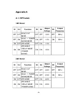

- -
10
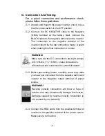
certain receptacles in residential installations. While the true
sine wave output of the Inverter is equivalent to the waveform
provided by utilities, compliance with UL standards requires us
to test and recommend specific GFCI’s. State power has tested
the following GFCI-protected 15A receptacles and found that
they functioned properly when connected to the output of the
Inverter.
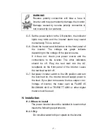
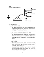
H-3. Making DC Wiring Connections:
Follow this procedure to connect the battery cables to
the DC input terminals on the Inverter. Your cables
should be as short as possible (ideally, less than 10
feet/ 3 meters) and large enough to handle the
required current, in accordance with the electrical
codes or regulations applicable to your installation.
Cables that are not an adequate gauge (too narrow) or
are too long will cause decreased inverter
performance such as poor surge capability and
frequent low input voltage warnings and shutdowns.
These low input voltage warning is due to DC voltage
drop across the cables from the inverter to the
batteries. The longer and narrower these cables, the
greater the voltage drop.
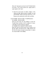
I. Operation:
To operate the power inverter, turn it on using the ON/ OFF
switch on the front panel. The power inverter is now ready to
deliver AC power to your loads. If you are operating several
loads from the power inverter, turn them on separately after
the inverter has been turned on. This will ensure that the
power inverter does not have to deliver the starting currents
for all the loads at once.