


Mechanical Installation
© Rice Lake Weighing Systems
●
All Rights Reserved
5
After considering any areas that may cause accuracy problems, follow these installation steps.
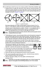
1. Determine where to position the mount and in which direction it should be oriented. The
preferred mounting orientation for single ended beams is with the longitudinal axis of the
load cell pointing toward the center of the vessel in circular mounting configurations as
illustrated in A and B in
.
Figure 2-1. Load Cell Orientation
Mounting configurations for square and rectangular vessels are shown in D an C in
Figure 2-1 For rectangular vessels, the load cell’s longitudinal axis should be aligned
along the vessel’s longest dimension as shown in Figure 4. In any application where a
recurring side force is present in one direction, such as in a conveyor belt or roller
platform, the longitudinal axis of the load cell should align with that force.
The load may be checked in one of two directions. Make sure the top plate moves in
the proper direction (see step 2).
2. To assemble each module, remove the load cell bolts, position the load cell, and pass the
load cell bolts through the load cell and the load cell spacer, and thread them into the
base plate. Lift the top plate (do not loosen the retaining bolts) and place the load button
into the load hole of the load cell. Rest the top plate on the load button. Verify that the
retaining bolts do not protrude above the plane of the top plate. Adjust if necessary.
During installation or transport, the jacking nuts may be used to isolate the top plate from
the load cell to avoid any damage to the load cell.
The load may be checked in one of two directions. To use the alternate
checking feature, lift the top plate clear of the load button, turn the load
button 90°, and restore the top plate to its original position.
3. Lift and block the vessel to the same height as the assembled mounts.
4.
Use the jacking nuts to fully raise the top plate, automatically ensuring
correct alignment of the top plate and base plate during installation.
5. Remove the block from one support point and slide a mount into position.
6. If the mount is being fitted under the leg of a vessel, verify that the leg’s center line
passes through the center of the load button.
7. Attach the top plate by bolting. Do not fully tighten as shimming may be
necessary to level
The threads in the top plate of the 5-250kg modules are 1/2”-20 N.F. threads. The
threads in the top plate of the 500-5000kg modules are 3/4”-10 N.C. threads.
A
B
C
D
Note
or
Note


