


Load Cell Wiring
© Rice Lake Weighing Systems
●
All Rights Reserved
7
3.0
Load Cell Wiring
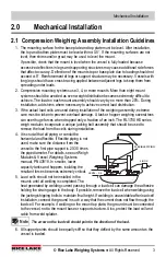
1. Route the load cell cables so they will not be damaged or cut. Cable should not be routed
near heat sources greater than 150° F.
Do not shorten any load cell cable.
The load
cell is temperature compensated with the supplied length of cable. Cutting the cable will
affect temperature compensation. Coil excess cable and protect it so it will not be
mechanically damaged or be sitting in water.
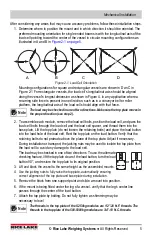
2. Provide a drip loop in all cables so that water or other liquids will not run directly down the
cables onto either the load cells or the junction box. Attach load cell cable to the dead
structure, not the vessel.
3. If conduit protection is necessary against mechanical or rodent damage to the load cell
cables, use flexible conduit and conduit adapters at the load cells.
4. Connect cables for RL9018SS, RLHTO, TEDEA 355, and TEDEA 3510 load cells to the
summing board in the junction box according to the guide shown below and the labels on
the terminal strips of the junction box. To verify the wiring scheme, see the certification
shipped with the load cell.
5. For better performance, use positive and negative remote sense lines if the wiring run
from the junction box to the indicator is longer than 25 feet.
RL9018SS, 355
RLHTO, 3510
Load Cell Wire
Color
Function
Load Cell
Wire Color
Function
Blue
+EXC
Blue
+EXC
Black
–EXC
Black
–EXC
White
+SIG
White
+SIG
Red
–SIG
Red
–SIG
Bare
SHIELD
Bare
SHIELD
Green
+Sen
Green
+Sen
Yellow
-Sen
Gray
-Sen
Table 3-1. Load Cell Wiring
Drip Loop


