


Mechanical Installation
© Rice Lake Weighing Systems
●
All Rights Reserved
3
2.0
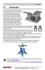
Mechanical Installation
2.1 Compression Weighing Assembly Installation Guidelines
1. The mounting surface for the base plate and top plate must be level. After installation,
the top and bottom plates must be level within ±0.5°. If the mounting surfaces are not
level, then shims and/or grout may be used to level the mount.
If possible, check that the mount is level when the vessel is fully loaded because
excessive deflections in legs and supporting structures may cause additional side forces
that affect accuracy. Deflection of the mounts top or base plate due to loading should not
exceed ±.5°. Reinforcement of legs or support structure may be necessary. Vessels with
long legs should have cross bracing applied between adjacent legs to keep them from
spreading under loads.
2. Compression mounting systems use 3, 4, or more mounts. More than eight mount
systems should be avoided as even weight distribution becomes extremely difficult to
achieve. The load on each mount assembly should vary by no more than 20%. During
installation, add shims where necessary to achieve correct load distribution.
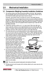
3. If the actual load cells are used during installation of the weighing assembly, extreme
care must be taken to prevent overload damage. A tank or hopper weighing several tons
can exert huge forces when dropped only a fraction of an inch. The RL1700 HE series
weigh modules incorporate a unique jacking bolt assembly that should be used to
remove the load from the cells during installation.
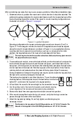
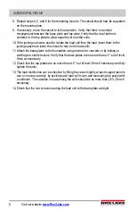
4. It is crucial that all piping or conduit be
horizontal and flexible. If flexible piping is not
used, make sure the distance from the
vessel to the first pipe support is 20-30 times
the pipe diameter. For details, see our Weigh
Modules & Vessel Weighing Systems
manual, PN 43918. In smaller, lower
capacity tanks and hoppers, isolating the
resultant forces becomes extremely critical.
5. Load cells should not be installed in the
mounts until all welding is completed. The
heat generated by welding current passing through a load cell can damage the adhesive
holding the strain gauge to the body. If possible, remove the load cell when welding using
the jacking/shipping bolts to maintain final height. If welding is unavoidable after load cell
installation, connect the ground in such a way that the current does not flow through the
load cell. For example, if welding on the mount top plate, the ground must be connected
to the vessel, not to the mount base or support structure. Also, protect the load cell and
cable from weld splatter.
The arrow on the load cell should point in the direction of the load.
6. All support points should be equally stiff so that they deflect by the same amount as the
vessel is loaded.
LEVEL - 0.5
FLEXIBLE PIPING
J-BOX
Note


