Rice Lake 420 Plus Скачать руководство пользователя страница 35

420 Plus Installation Manual - Calibration

31

Repeat for up to five linearization points. To 
exit the linearization parameters, press   to 
return to WLIN.

Millivolt Calibration: If millivolt calibration 
is enabled press   to display and edit the test 
weight value, press   again to display and 
edit the millivolt value for that weight, press 

 again to calibrate and display the raw A/D 

count, press   again to move to the next 
calibration point.

7. The rezero function is used to remove a 

calibration offset when hooks or chains are 
used to hang the test weights. 

• If no other apparatus was used to hang the test 

weights during calibration, remove the test 
weights and press   to return to the CALIBR 
menu. 

• If hooks or chains were used during 

calibration, remove these and the test weights 
from the scale. With all weight removed, 
press   to rezero the scale. This function 
adjusts the zero and span calibration values. 
The indicator displays 

*CAL*

 while the zero 

and span calibrations are adjusted. When 
complete, the adjusted A/D count for the zero 
calibration is displayed. Press   to save the 
value, then press   to return to the CALIBR 
menu.

8. Press 

 until the display reads 

CONFIG

, then 

press   to exit setup mode.

4.2

EDP Command Calibration

To calibrate the indicator using EDP commands, the 
indicator EDP port must be connected to a terminal or 
personal computer. See Section 2.3.5 on page 9 for 
EDP port pin assignments; see Section 5.0 on page 33 
for more information about using EDP commands.

Once the indicator is connected to the sending device, 

1. Place the indicator in setup mode (display 

reads 

CONFIG

) and remove all weight from the 

scale platform. If your test weights require 
hooks or chains, place them on the scale for 
zero calibration. 

2. Send the WZERO EDP command to calibrate 

zero. The indicator displays 

*CAL*

 while 

calibration is in progress.

3. Place test weights on the scale and use the 

WVAL command to enter the test weight 
value in the following format:

 WVAL=

nnnnnn

<CR> 

4. Send the WSPAN EDP command to calibrate 

span. The indicator displays 

*CAL*

 while 

calibration is in progress.

5. Up to five linearization points can be 

c a l i b r a t e d   b e t w e e n   t h e   z e r o   a n d   s p a n  

c a l i b r a t i o n   v a l u e s .   U s e   t h e   f o l l o w i n g  
commands to set and calibrate a single 
linearization point:

WLIN.V1=

nnnnn

<CR> 

WLIN.C1<CR>

The WLIN.V1 command sets the test weight 
value (

nnnnn

) for linearization point 1. The 

WLIN.C1 command calibrates the point. 
Repeat using the WLIN.V

x

 and WLIN.C

x

commands as required for additional 
linearization points.

6. To remove an offset value, clear all weight 

from the scale, including items used to hang 
test weights, then send the REZERO EDP 
command. The indicator displays 

*CAL*

 while 

the zero and span calibrations are adjusted. 

7. Send the KUPARROW EDP command to exit 

setup mode. 

4.3

Revolution Calibration

To calibrate the indicator using 

Revolution

, the 

indicator EDP port must be connected to a PC running 
the 

Revolution

 configuration utility.

Use the following procedure to calibrate the indicator:
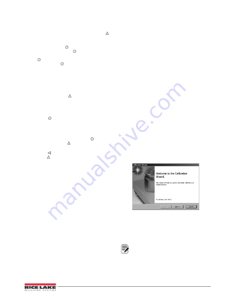
1. Select 

Calibration Wizard

 from the 

Revolution


tools menu.

2.

Revolution

 uploads calibration data from the 

indicator then presents the information in the 
calibration wizard, as shown in Figure 4-2 

Figure 4-2. 

Revolution

 Calibration Display

3. Enter the 

Value of Test Weight

 to be used for 

span calibration then click 

OK

4. The Zero Calibration dialog box prompts you 

to remove all weight from the scale. Clear the 
scale and click 

OK

 to begin zero calibration.

If your test weights require hooks or 
chains, place them on the scale for zero 
calibration.

5. When zero calibration is complete, the Span 

Calibration dialog box prompts you to place 
test weights on the scale for span calibration. 
Place tests weights on the scale then click 

OK

.

Note

Содержание 420 Plus

Страница 1: ...85127 420 Plus HMI Digital Weight Indicator Version 1 14 Installation Manual...

Страница 2: ......

Страница 3: ...ed Tare Value 3 1 4 7 Acquire Parts Sample 4 1 4 8 Display Part Weight 4 1 4 9 Display Accumulator 4 1 4 10 Display or Change Time 4 1 4 11 Display or Change Setpoint Value 4 1 4 12 Turn Setpoint On o...

Страница 4: ...5 2 Saving and Transferring Data 38 5 2 1 Saving Indicator Data to a Personal Computer 38 5 2 2 Downloading Configuration Data from PC to Indicator 38 6 0 Print Formatting 39 6 1 Print Formatting Com...

Страница 5: ...20 4 20 mA tracking of gross or net weight values Available in 115 VAC and 230 VAC versions Available in DC power version The 420 Plus is NTEP certified and pending Measurement Canada approval for Cl...

Страница 6: ...Gross weight is within 0 25 graduations of zero This annunciator lights when the scale is zeroed Standstill Scale is at standstill or within the specified motion band Some operations including tare fu...

Страница 7: ...tween primary and secondary units The appropriate units LED to the right of the display is lit 1 4 3 Zero Scale 1 In gross mode remove all weight from the scale and wait for the standstill annunciator...

Страница 8: ...date press the TIME DATE key once press TIME DATE a second time to display the time To set the date press the TIME DATE key once Use the numeric keypad to enter the date then press the ENTER key Use t...

Страница 9: ...N 42149 Three reducing glands PN 15664 One capacity label PN 42350 Three each of grounding clamps PN 53075 external tooth lock washers PN 15133 and kep nuts PN 14626 for cable shield grounding against...

Страница 10: ...se the braid where the cable passes through the clamp see Figure 2 2 For load cell cables cut the shield wire just past the grounding clamp Shield wire function is provided by contact between the cabl...

Страница 11: ...420 Plus Installation Manual Installation 7 Figure 2 4 420 Plus CPU and Power Supply Board...

Страница 12: ...runs voltage drop over the power conductor needs to be considered See table and formula below to compute voltage drop VDROP 2 85A x 1000ft length of run in ft 2 85A maximum current draw from DC DC po...

Страница 13: ...board see Figure 2 4 Use cable ties to secure serial cables to the inside of the enclosure The EDP port supports full duplex RS 232 communications only the serial port provides either active 20 mA ou...

Страница 14: ...kplate over the enclosure and reinstall the backplate screws Use the torque pattern shown in Figure 2 6 to prevent distorting the backplate gasket Torque screws to 15 in lb 1 7 N m Figure 2 6 420 Plus...

Страница 15: ...lt stand 1 11 44676 Sealing washer 1 12 42640 Screws 1 4 28NF X 1 4 2 13 19538 Cable grip plugs 2 14 15626 Cable grips 3 15 30375 Nylon seal rings for cable grips 3 16 85202 Power cord assembly 115 VA...

Страница 16: ...lation Manual Figure 2 8 420 Plus Overlay and Power Supply 20 21 22 To J7 header on PC Board 6 From Power Cord 16 23 28 5 pin overlay 8 pin overlay Ground Wire Detail 25 27 24 To backplate 3 From powe...

Страница 17: ...420 Plus Installation Manual Installation 13 Figure 2 9 420 Plus Enclosure Backplate and CPU Board 1 2 3 4 5 6 7 8 9 10 12 11 13 14 15 16 17 18 32 30...

Страница 18: ...ay Revolution supports both uploading and downloading of indicator configuration data This capability allows configuration data to be retrieved from one indicator edited then downloaded to another To...

Страница 19: ...d overload tare function sample rate and digital filtering parameters FORMAT Format Set format of primary and secondary units display rate CALIBR Calibration Calibrate indicator See Section 4 0 on pag...

Страница 20: ...ad see Figure 3 4 Figure 3 4 Editing Procedure for Numeric Values 3 2 Menu Structures and Parameter Descriptions The following sections provide graphic representations of the 420 Plus menu structures...

Страница 21: ...gal value varies depending on local regulations For scales using linear calibration do not set the zero tracking band to a value greater than that specified for the first linearization point ZRANGE 1...

Страница 22: ...immediate area of the scale Choices indicate the number of A D conversions that are averaged to obtain the displayed reading A higher number gives a more accurate display by minimizing the effect of a...

Страница 23: ...u parameter descriptions DSPRAT 250MS 500MS 750MS 1SEC 1 5SEC 2SEC 2 5SEC 3SEC 4SEC 6SEC 8SEC Display rate Sets the update rate for displayed values Values are in milliseconds MS or seconds SEC Table...

Страница 24: ...88 88 Decimal point location Determines the location of the decimal point or dummy zeros in the secondary unit display DSPDIV 5D 1D 2D Display divisions Selects the value of minimum division size of t...

Страница 25: ...ivolt calibration press ENTER to display and edit the test weight value Press ENTER again to display and edit the millivolt value for that weight Press ENTER a third time to calibrate and display the...

Страница 26: ...TE INDUST LFT Specifies stream rate Stream rate can be set to industrial or legal for trade PRNDES EDP PRN BOTH Print destination Selects the EDP port printer port or both ports simultaneously for dat...

Страница 27: ...rameter Choices Description Table 3 5 Serial Menu Parameters Continued Note XXXXXXX XXXXXXX PWRUPM GO OIML REGULA 000000 number CONSNU DELAY SETPNT PROGRM PFORMT SERIAL CALIBR CONFIG FORMAT 000000 num...

Страница 28: ...value Specifies the initial consecutive number CONSNU value used when the consecutive number is reset by sending CLRCN digital input UID 1 Specifies the unit identification number any numeric value up...

Страница 29: ...ORMAT Display and edit active character and ASCII value Delete active character Scroll left in formatting string Increment ASCII value of active character Decrement ASCII value of active character Pre...

Страница 30: ...an the setpoint value or is within or outside of the band value LOWER means the output is active until you reach weight If trip is HIGHER the output is active when the setpoint is met or exceeded INBA...

Страница 31: ...resets the consecutive number to the value specified on the CONSTU parameter PROGRM menu KBDLOC disables the keypad while the digital input is held low HOLD holds the current display Releasing this in...

Страница 32: ...20 mA output Select 0 for 0 10 V output select 20 for 4 20 mA output ERRACT FULLSC HOLD ZEROSC Error action Specifies how the analog output responds to system error conditions Possible values are FULL...

Страница 33: ...The VERS menu is used to check the software version and reg version installed in the indicator You can also check the indicator model Figure 3 14 Version Menu XXXXXXX ALGOUT XXXXXXX XXXXXXX Software v...

Страница 34: ...he test weights to be used for the span calibration Press to store the entered WVAL value and go to span calibration WSPAN 5 With WSPAN displayed place test weights on the scale and press to calibrate...

Страница 35: ...rate zero The indicator displays CAL while calibration is in progress 3 Place test weights on the scale and use the WVAL command to enter the test weight value in the following format WVAL nnnnnn CR 4...

Страница 36: ...ficients 4 4 1 Adjusting Final Calibration Calibration may be affected by environmental factors including wind vibration and angular loading For example if the scale is calibrated with 1000 lb a strai...

Страница 37: ...used in both setup and weighing mode Several of the commands serve as pseudo keys providing functions that are not represented by a key on the front panel For example to enter a 15 pound tare weight...

Страница 38: ...r the equal sign If you type an incorrect command or value the display reads Changes to the parameters are saved as they are entered but typically do not take effect until you exit setup mode For exam...

Страница 39: ...on REZERO Rezero LC CD Set deadload coefficient value LC CW Set span coefficient value Table 5 5 CALIBR EDP Commands Command Description Values EDP BAUD EDP port baud rate 300 600 1200 2400 4800 9600...

Страница 40: ...ription Values GFMT Gross demand print format string See Section 6 0 on page 39 for detailed information NFMT Net demand print format string CFMT Count demand print format string Table 5 8 PFORMT EDP...

Страница 41: ...mmand Description Response Format UID Set unit ID nnnnnnn SD Set date MMDDYY DDMMYY YYMMDD enter using DATEFMT specified ST Set time hhmm enter using 24 hour format SX Start EDP streaming OK or EX Sto...

Страница 42: ...parameters to the PC as ASCII formatted text 5 2 2 Downloading Configuration Data from PC to Indicator Configuration data saved on a PC or floppy disk can be downloaded from the PC to an indicator Th...

Страница 43: ...each print format string includes the output field length of the print formatting commands not the command length For example if the indicator is configured to show a decimal point the G command gener...

Страница 44: ...is format might look like the following FINE TRANSFER CO 32400 WEST HIGHWAY ROAD SMALLTOWN 1345 lb GROSS 6 2 2 Using the Front Panel If you have no access to equipment for communication through the ED...

Страница 45: ...he print format without the formatting commands NL and SP required by the front panel or EDP command methods Using Revolution you can type text directly into the grid then select weight value fields f...

Страница 46: ...Printer format checksum error Call RLWS Service LCCKSM Load cell calibration checksum error Recalibrate load cells EIDATA Internal RAM checksum error Call RLWS Service E REF A D reference error A D c...

Страница 47: ...y query which annunciators are currently displayed on the indicator front panel The ZZ command returns the currently displayed weight and a decimal number representing the LED annunciators currently l...

Страница 48: ...Figure 7 1 Continuous Output Data Format STX POL wwwwwww UNIT G N S TERM ASCII 02 decimal Weight data 7 digits right justi ed with decimal point leading zero supression Overload Underrange Display ove...

Страница 49: ...CK 06 06 38 26 F 70 46 f 102 66 Ctrl G BEL 07 07 39 27 G 71 47 g 103 67 Ctrl H BS 08 08 40 28 H 72 48 h 104 68 Ctrl I HT 09 09 41 29 I 73 49 i 105 69 Ctrl J LF 10 0A 42 2A J 74 4A j 106 6A Ctrl K VT 1...

Страница 50: ...CB 235 EB 140 8C 1 4 172 AC 204 CC 236 EC 141 8D 173 AD 205 CD 237 ED 142 8E 174 AE 206 CE 238 EE 143 8F 175 AF 207 CF 239 EF 144 90 176 B0 208 D0 240 F0 145 91 177 B1 209 D1 241 F1 146 92 178 B2 210...

Страница 51: ...anel Display Characters Figure 7 2 shows the 7 segment LED character set used to display alphanumeric characters on the 420 Plus front panel Figure 7 2 420 Plus Display Characters 9 E Q F R G S 0 H T...

Страница 52: ...s and the secondary decimal point is set to 8888 88 the indicator will overflow if 5 tons or more are applied to the scale With 5 tons applied and a conversion factor of 2000 the secondary units displ...

Страница 53: ...tering effect is 20 4 8 8 With this configuration each A D reading has a 1 in 20 effect on the displayed weight value Setting the filters to 1 effectively disables digital filtering 7 7 2 DFSENS and D...

Страница 54: ...cause more consecutive out of band readings so DFSENS should be set higher to counter low frequency transients Reconfigure as necessary to find the lowest effective value for the DFSENS parameter 7 8...

Страница 55: ...the front panel key functions in test mode Note that because the Test Menu functions are all on a single menu level the GROSS NET key has no function Press the ZERO key to exit test mode Table 7 7 sum...

Страница 56: ...emory Test Green Pass Red Fail LED ANA Red Not Implemented Analog Option Card Digital Input Output Status DO 1 Digital Out 1 On when lit active low DO2 Digital Out 2 On when lit active low DI 1 Digita...

Страница 57: ...erload 12 V continuous static discharge protected RFI Protection Signal excitation and sense lines protected by capacitor bypass Analog Output Optional fully isolated voltage or current output 14 bit...

Страница 58: ...t caused by accident misuse neglect alteration improper installation improper repair or improper testing RLWS shall be the sole judge of all alleged non conformities Such equipment has not been modifi...

Страница 59: ......

Страница 60: ...PN 85127 05 12...

Отзывы: