


14
420 Plus Installation Manual
3.0
Configuration
To configure the
420 Plus
indicator, the indicator must
be placed in setup mode. The setup switch is accessed
by removing the large fillister head screw on the
enclosure bottom. Switch position is changed by
inserting a screwdriver or similar tool into the access
hole and pressing the setup switch.
When the indicator is placed in setup mode, the word
CONFIG
is shown on the display. The CONFIG menu
is the first of ten main menus used to configure the
indicator. Detailed descriptions of these menus are
given in Section 3.2 on page 16. When configuration
is complete, return to the CONFIG menu and press the
(
ZERO
) key to exit setup mode, then replace the
setup switch access screw.
3.1
Configuration Methods
The
420 Plus
indicator can be configured by using the
front panel keys to navigate through a series of
configuration menus or by sending commands or
configuration data to the EDP port. Configuration
using the menus is described in Section 3.1.3 on
page 15.
C o n f i g u r a t i o n u s i n g t h e E D P p o r t c a n b e
accomplished using either the EDP command set
described in Section 5.0 or the
Revolution
®
software.
3.1.1
Revolution Configuration
The
Revolution
configuration utility provides the
preferred method for configuring the
420 Plus
indicator.
Revolution
runs on a personal computer to
set configuration parameters for the indicator. When
Revolution
configuration is complete, configuration
data is downloaded to the indicator.
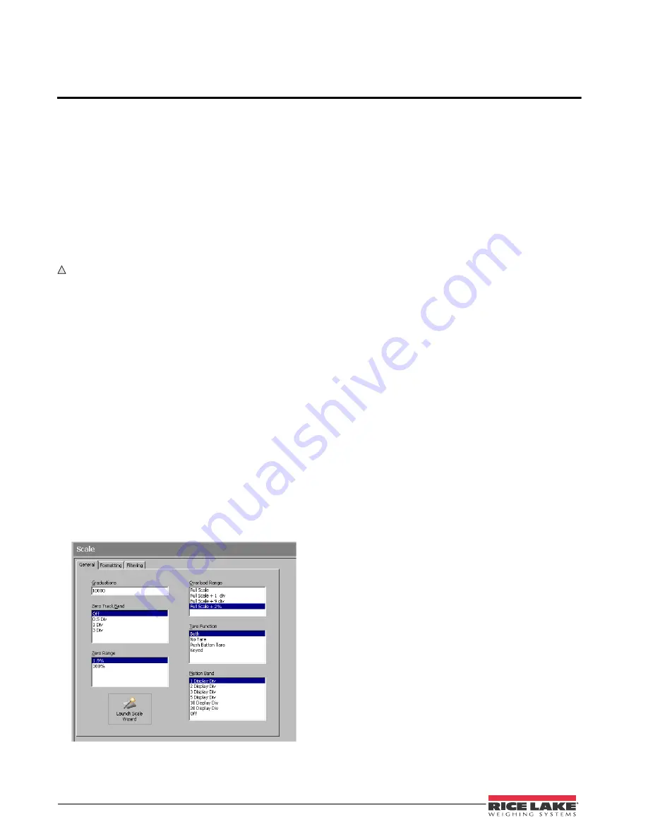
Figure 3-1. Sample
Revolution
Configuration Display
Revolution
supports both uploading and downloading
of indicator configuration data. This capability allows
configuration data to be retrieved from one indicator,
edited, then downloaded to another.
To use
Revolution
, do the following:
1. Install the
Revolution
module on an
IBM-compatible personal computer running
Windows
®
98 or later. Minimum system
requirements are 4MB of extended memory
and at least 5MB of available hard disk space.
2. With both indicator and PC powered off,
connect the PC serial port to the indicator
EDP port.
3. Power up the PC and the indicator. Use the
setup switch to place the indicator in setup
mode.
4. Start the
Revolution
program.
Figure 3-1 shows an example of one of the
Revolution
configuration displays.
Revolution
provides online help for each of its
configuration displays. Parameter descriptions
provided in this manual for front panel configuration
can also be used when configuring the indicator using
Revolution
: the interface is different, but the
parameters set are the same.
3.1.2
EDP Command Configuration
The EDP command set can be used to configure the
420 Plus
indicator using a personal computer,
terminal, or remote keyboard. Like
Revolution
, EDP
command configuration sends commands to the
i n d i c a t o r E D P p o r t ; u n l i k e
Re vo lu t i o n
, E D P
commands can be sent using any external device
capable of sending ASCII characters over a serial
connection.
EDP commands duplicate the functions available
using the indicator front panel and provide some
functions not otherwise available. EDP commands can
be used to simulate pressing front panel keys, to
configure the indicator, or to dump lists of parameter
settings. See Section 5.0 on page 33 for more
information about using the EDP command set.
Содержание 420 Plus
Страница 1: ...85127 420 Plus HMI Digital Weight Indicator Version 1 14 Installation Manual...
Страница 2: ......
Страница 11: ...420 Plus Installation Manual Installation 7 Figure 2 4 420 Plus CPU and Power Supply Board...
Страница 59: ......
Страница 60: ...PN 85127 05 12...


