31
C
A/C Thermostat
A/C Outdoor Unit
G
Field Installed
Line Voltage
-
WIRING INFORMATION
Factory Standard
-
Y
C
W/BL
W1
G
Air Handler
R
Y
W2
G/BK
Y
W/BK
BR
R
R
Y
W2
W
C
**
*
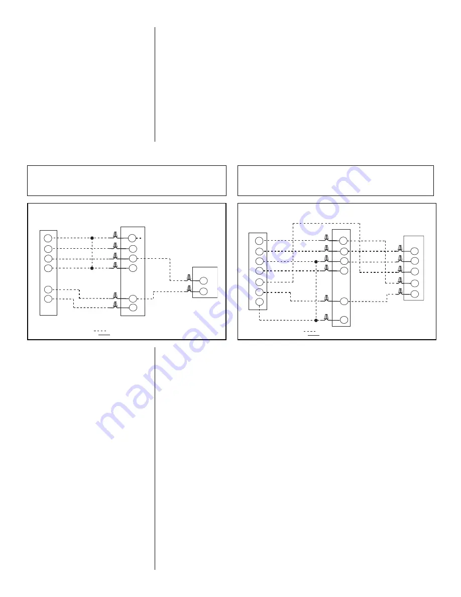
FIGURE 13
TYPICAL THERMOSTAT: STRAIGHT COOLING W / ELECTRIC HEAT
C
Heat Pump
Thermostat
Heat Pump
Outdoor Unit
D
B
G
Field Installed
Line Voltage
-
WIRING INFORMATION
Factory Standard
-
B
E
Y
R
C
R
W1
C
G
Air Handler
R
Y
W2
Y
W/BK
G/BK
BR
W/BL
R
Y
W2
**
*
FIGURE 14
TYPICAL THERMOSTAT: HEAT PUMP W / ELECTRIC HEAT
**
For 13kW or higher, W1 and W2
can be connected together for
maximum outlet temperature rise.
*(-)H1P has no Y connection.
Connect Y on outdoor unit directly
to Y on thermostat on (-)H1P.
*(-)H1P has no Y connection.
Connect Y on outdoor unit directly
to Y on thermostat on (-)H1P.
**
For 13kW or higher, W1 and W2
can be connected together for
maximum outlet temperature rise.
WIRE COLOR CODE:
BK - BLACK G - GREEN P - PINK W - WHITE
BR - BROWN GY - GRAY PR - PURPLE Y - YELLOW
GL - BLUE O - ORANGE R - RED
NOTE:
These low voltage application diagrams are generic. Your
indoor/outdoor units may not have all the characteristics shown or may
not wire exactly as shown. Refer to the diagrams and information sent
with your indoor/outdoor sections.
3.13.9 THERMOSTAT & CONTROL WIRING CONNECTIONS
3.14 AIRFLOW
Airflow performance data is based on a dry indoor coil and no return air filter in place. Select
performance table for appropriate unit size, voltage and number of electric heaters to be
used. Make sure external static applied to unit allows operation within the minimum and
maximum limits shown in Section 3.14.1 below for both cooling and electric heat operation.
For optimum blower performance, operate the unit in the .3 to .7 in W.C. external static
range. Units should be applied with a minimum of .1 in W.C. external static pressure.
NOTE:
The air-flow performance data tables (see Section 3.14.3) list air-flow information for
air-handlers without heater and with maximum heater kW allowed for each model. The fol-
lowing formula can be used to calculate the adjusted CFM for smaller kW heaters.
Adjusted CFM = No Heat CFM – [(No Heat CFM – Max kW CFM) × ––––––––]
Actual kW
Max kW
3.13.8 CONTROL WIRING
IMPORTANT:
Class 2 low voltage control wire should not be run in conduit with power
wiring and must be separated from power wiring, unless class 1 wire of proper voltage
rating is used.
• Low voltage control wiring should be 18 Awg. color-coded. For lengths longer than
100 ft., 16 Awg. wire should be used.
• Low voltage control connections are made to low voltage pigtails extending from top
of air handler (upflow position - see Figure 3). Connections for control wiring are
made with wire nuts. Control wiring knockouts (5/8 and 7/8) are also provided on the
right and left side of the unit for side connection.
• See Section 3.13.9 below for control wiring connections.
• Make sure, after installation, separation of control wiring and power wiring has been
maintained.
• See Section 3.13.1 for how to reconfigure transformer for 208 volt applications.


