background image


12/27 


System Setting 

Click “System Setting” in the main interface: 


1.


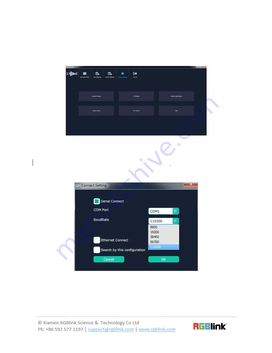
Connect Setting 


Click “Connect Setting”: Select ”COM Port” and “Baud


Rate”, click the drop down 

arrow after them, and click “OK”.   


Setting  the  device  connecting  ways:  Serial  Connect,  Ethernet  Connect  and 
Search by this configuration. 


Содержание FLEX RS1

Страница 1: ...tion Edge Blending and Splicing Independent output scaling to any aspect or resolution Rotation Any degree rotation for each of the output Edge Blending Independent edge blending for each output Splicing Image splicing for each 2K output Cascade multiple units for additional screens Control Support Art Net DMX512 A RS 232 IP TCP UDP Manage with XPOSE on Windows M a c O S i O S ...

Страница 2: ...re Operation 7 Software Installation 7 Environment Requirements 7 Software Operation 10 Login to the Software 10 Web Links 11 Connect Setting 11 System Setting 11 Input Settings 15 Output Settings 15 Operation Mode 18 Logout 25 Contact Information 27 Zhu Maggy 1 Deleted 12 Zhu Maggy 1 Deleted 12 Zhu Maggy 1 Deleted 12 ...

Страница 3: ...nputs a dual link DVI input a Display Port input and four DVI outputs FLEX RS1 supports up to 4K2K the UHD input resolution Different resolutions can be set in each output FLEX RS1 features in multiple cascade and simple managed by XPOSE software System Connection RGBlink video processing solutions provide a range of flexible configuration options for professional applications ...

Страница 4: ...ower Cable RJ45 to DB9 Cable RJ45 to RS232 RS232 to USB Cable Packing Configuration Note AC Power Cable supplied as standard according to destination market USB Cable HDMI Cable Antistatic Bag DVI to HDMI Cable ...

Страница 5: ...re Orientation Front Panel Panel Instruction SIGNAL Signal indicator lights when device has connected with input signal USB Interface To upgrade the device POWER Power indicator lights when device has power supply ...

Страница 6: ...Interface 4 4 DVI outputs Control Interface 2 SLAVE IN Connect to XPOSE software by RS 232 RGBlink supports a USB to RS 232 converter and the RS 232 to RJ45 cable for this connection as standard accessories 5 ART NET IN Connect to ARTNET controller 6 ART NET loop Connect to another equipment to make mutiple cascade Power Connection 3 Power Switch 7 AC 85 264V 50 60HZ ...

Страница 7: ...irements Windows Operation System Windows 7 8 10 Processor 1GHz 32 bit or 64 bit processor Memory 2Gb Hard Disk 16Gb Graphics 128Mb DirectX9 Display 1280X720 Mac Operation System Mac OS Processor 1 0GHz Memory 512M Hard Disk 512M Graphics 512M Display 1366x768 ...

Страница 8: ... Installer Language box select the language for example select English and click OK to confirm It will pop up the installer box and click Next to install as follows 2 Select Browse to select the XPOSE software install location and click install ...

Страница 9: ...9 27 3 User should get the rights in Roles Management when install the software to disk C if the system is Windows 7 or above 4 Click Finish and is ready to run the XPOSE management software ...

Страница 10: ... the interface The user name is Admin and defaultly there is no password Select FLEX RS1 select language English and enter the software by clicking Login 2 If user wants to change the language to Chinese click the drop down arrow after Language and select Chinese then click Login to enter the software ...

Страница 11: ... and Log out In the following parts come with the detail Web Links XPOSE management software sets up the web links Click the web links icon on the top left corner and goes access to RGBlink website Connect Setting The remote controller PC which runs XPOSE connects with Flex RS1 by the USB to the RS 232 converter and the RS 232 to RJ45 cable with the standard accessories ...

Страница 12: ... in the main interface 1 Connect Setting Click Connect Setting Select COM Port and Baud Rate click the drop down arrow after them and click OK Setting the device connecting ways Serial Connect Ethernet Connect and Search by this configuration ...

Страница 13: ... Click the IP Settings and pop up window as follows Default Auto get IP address Users can also set IP address Mask and GateWay manually This is usually used if one computer control some devices or remote control It takes effect after reboot the software if change IP through network ...

Страница 14: ...ation and pop up window as follows Display the device version information Including Model Number Serial Number IP Address firmware version etc 4 Factory Reset Click Factory Reset and pop up window as follows Click OK or Cancel to confirm the reset ...

Страница 15: ... Control Click Fan Control and pop up window as follows Enable or disable the Auto Fan Control set Fan Speed and click Set that will load Input Settings Click the Input Settings and enter the interface as follows ...

Страница 16: ...as follows Click Work Mode click the drop down arrow after the Mode and select 4K x 2K or 4K x 1K or 2K x 1K Click Input 1 Type Including Dual DVI HDMI 1 4 HDMI 2 0 DP 1 2 Then click set Output Settings Click the Output Settings and enter the interface as follows ...

Страница 17: ...lick the Test Pattern and pop up window as follows Click Output click the drop down arrow and select any Ports among the four boards Click Color Choose click the drop down arrow and select any color among the sixteen boards ...

Страница 18: ...ect one port or all ports and enable the DE function by sliding the DE Switch The settings for DE include X Y width height line polarity and scene polarity Vertical spliting can be selected in Output Port Operation Mode Click the Operation Mode and enter the interface as follows There is 3 working modes including the Video Wall mode Rotation mode and Blending Mode ...

Страница 19: ...he size and location of the layer a Drag the layer by mouse click the right window select any layer press the rim of the layer with mouse to drag the size release the mouse click the layer again and press the mouse to drag the layer to suitable position b Choose number directly click the left or right window select any layer and choose any number as X Y W H to ensure accurate position and size Out...

Страница 20: ...n arrow and select any port among the four boards This mode allow set each port resolution independently Click resolution click drop down arrow and select any resolution among the sixteen boards Width Height and Frequency can be set ...

Страница 21: ...t by sliding the switch 2 Rotation Mode Click the Rotation Mode and pop up window as follow the monitor on the left can rotate the layer on the right Click monitor 1 4 click W and H to set size Choose W as 1920 and choose H as 1080 Rotation click the left window select any monitor click R and choose any angle Each monitor rotates as setting angles Layer 1 4 X Y for Layer position W Y is Layer size...

Страница 22: ...the mouse click the layer again and press the mouse to drag the layer to suitable position b Choose number directly click the left or right window select any layer and choose any number as X Y W H to ensure accurate position and size Click the Sync to viewfinder shortcut to synchronise display layer with viewfinder Click the Sync to viewfinder shortcut to synchronise finder frame with display laye...

Страница 23: ...drag the size release the mouse click the layer again and press the mouse to drag the layer to suitable position b Choose number directly click the left or right window select any layer and choose any number as X Y W H to ensure accurate position and size Projection Mode supports to reduce the blur of image rim and the fusion split Click left or right window select any layer and choose any number ...

Страница 24: ... shortcut to synchronise finder frame with display layer Sync Click the sync shortcut to synchronize the current data Shortcut Keys Click the shortcut and pop up window as follows Load Script Click the load script shortcut user can load the data from the computer Save Script Click the save script shortcut user can save the data to the computer Reset Click the Reset shortcut to reset settings ...

Страница 25: ...Take function Auto take on is the default state Click Cut or Take the preview will be cut or seamless switch to the display Logout Click Logout to exit the XPOSE sorftware and pop up window as follows Click cancel or OK to confirm User also can be click the right corner red button to exit software directly ...

Страница 26: ...elivery date to customer and are non transferable RGBlink warranties are only valid to the original purchase owner Warranty related repairs include parts and labor but do not include faults resulting from user negligence special modification lighting strikes abuse drop crush and or other unusual damages The customer shall pay shipping charges when unit is returned for repair ...

Страница 27: ...e S601 Weiye Building Torch Hi Technology Zone Xiamen Fujian China 361006 PH 86 592 5771197 Fax 86 592 5788216 E mail Support support rgblink com Sales sales rgblink com Web Support www rgblink com contact us Sales www rgblink com support ...

Отзывы: